Teaching students about logic gates is often done in two parts, once on the whiteboard for the theory, and again on the breadboard for the practice. [shurik179] wasn’t a fan of the abstraction between easy-to-understand symbols on the whiteboard, and small IC packages full of many gates in reality. Instead, he built a set of real-world logic gates that can be wired together as a teaching tool.
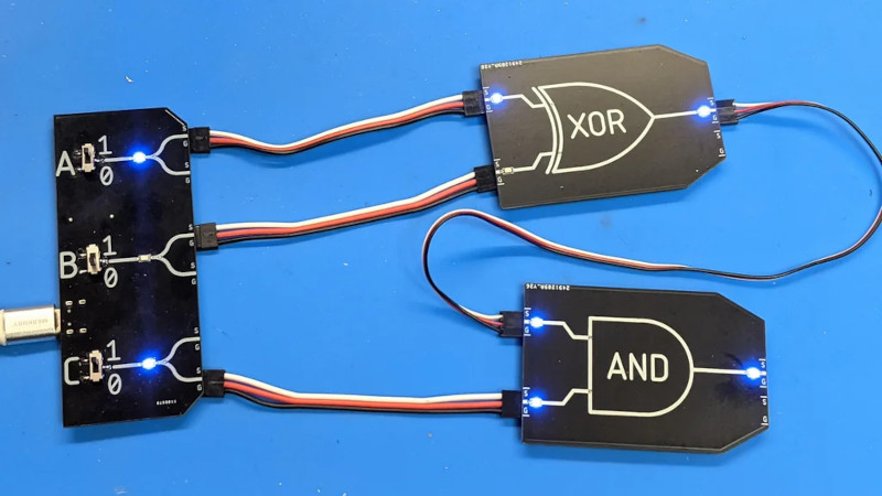
Each “gate’ consists of a PCB roughly the size of a business card that features LEDs to indicate the state of its inputs and outputs, and a silkscreen indicating the name and symbol of the gate in question. There’s also a master PCB, which features three seed values, A, B, and C, to feed into the system. Students can set these values to 1 or 0, and feed them into the gates, which are wired together with 3-conductor servo cables, and observe the input on the built-in LEDs.
It’s a great way to demonstrate logic gates in the classroom. The design also allows the PCBs to be flipped over to show the actual electronic components responsible for implementing the logic, serving as a great bridge towards better understanding of real electronic design. Of course, it’s not the only way to learn – even Fallout 4 has a fully fledged logic toolkit these days!


The double wires are a bit aesthetically displeasing. I know, that’s not trivial to dodge. Maybe use a thin coax/microphone cable. Or some other trick for a shared ground. Just for looks, you know, cause the PCB’s look pretty neat.
Heatshrink?
3.5mm audio jack and cables would work well for this
yeah.. but it is also the question of price. 3-wire servo cables are widely available and cheap. ZI keep looking for other options.
So cool and intuitive! :)
This is awesome :-)
I think it would have been good if the pcb was sized and the contacts were placed in a way that direct connections without cables would be posible. For that you would have to switch to male-female connectors of cause but it would also mean that you can’t easily short connections. Also I would have loved additional vertical connection points, at least at the output to make branching easier.
There are indeed additional connection points – each boards has two outputs (connected to same signal), it is just not shown on top silkscreen.
As for connecting without cabbles…I didn’t find a good way of doing it, and in any case it would be very restrictive. Sparkfun tried that, but I was not happy with the result.
If Minecraft used standard logic gates instead of “Redstone” …
Good memories. I made a 6 bit full adder in minecraft when I was in my teens. Truly an amazing learning experience.
I recall playing with mods that add logic gates, flip-flops, and more sensible color-coded wires. That might make for some good educational experiences. That being said, I still love classic redstone. I am currently working on creating a purposefully terrible redstone computer, and redstone mechanics are just different enough to make designing even “simple” parts like buses interesting.
You can build all the standard logic gates, and a few more complex ones, out of redstone if you’re not afraid of reading.
Reminds a little of LogicBots™.
https://store.steampowered.com/app/290020/LogicBots/
i like the idea but honestly i’d rather just have a sticker to put on a 74xx quad gate that gives the same information, and then just use a breadboard so i don’t have to solve the connector problem. much less expensive and on the order of 90% as easy to use, in my head anyways.
my feelings about connectors have evolved some since my childhood 101 projects kit with spring-coil terminals, i guess
It’s an educational product, most readers on HAD can handle DIP chips and wire up a breadboard if given a diagram. A subset of them can actually read a datasheet, and a subset of them can deal with SMD components. These aren’t for those people.
This is a toy I can give to my 8 year old niece and have them play with. I don’t need to worry about their aunt getting mad if they step on a DIP part and wind up with perfectly spaced 0.1″ holes in their skin, and since the power, ground, and any other passives are all hidden they only need to learn about a logic gate rather than the dozen or so other concepts that are separating you from an AND gate and a 7408 causing a blinking LED to work if you’re buying parts like this: https://www.jameco.com/z/7408-Major-Brands-IC-7408-Quad-2-Input-Positive-AND-Gate_49146.html and your only reference is: https://www.jameco.com/Jameco/Products/ProdDS/49146.pdf
8 year old kids can handle electronic parts and breadboards and will grasp the basic concepts of digital logic in no time. get rid of that problematic auntie instead…
Indeed, it was intended as demonstration kit for kids who are seeing it for the first time in their life, to get them interested. Once they are hooked, then some of them will progress to breadboards.
Until December someone has built a cpu out of it. Nice project
I love the use of R/C servo cables. Is that for GND, Vcc and signal? So just like a servo. Brilliant!
But what it it’s the 1990s and one manufacturer wires them backwards just to be jerks?
Actually, on second thoughts, it would be better to use female connectors for outputs and male for inputs on the boards in order to prevent two outputs being wired together and then to use Male to Female jumper wire with something like this (https://www.aliexpress.com/item/4001162140686.html) rebuilt with 3-way housings. It’s easy to non-destructively re-wire those DuPont style connectors with something sharp.
Unless the children you’re working with treat delicate things better than most, something like a reduced version of the DEC H-500 I used in high school might hold up better. Ours was almost 10 years old when I found it in a closet, and while it had obviously seen a lot of use, it still worked.