Just how tight are the manufacturing tolerances of modern FDM printer filament. Inquiring minds want to know, and when such minds are attached to handy fellows like [Thomas Sanladerer], you end up with something like this home-brew filament measurement rig to gather the data you seek.
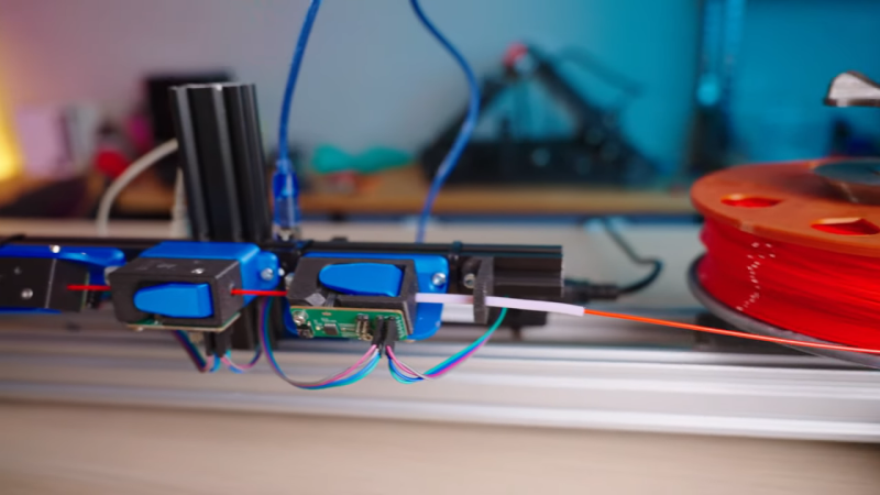
The heart of this build is not, as one might assume, some exotic laser device to measure the diameter of filament optically. Those exist, but they are expensive bits of kit that are best left to the manufacturers, who use them on their production lines to make sure filament meets their specs. Rather, [Thomas] used a very clever homemade device, which relies on a Hall effect sensor and a magnet on a lever to do the job. The lever is attached to a roller bearing that rides on the filament as it spools through the sensor; variations in diameter are amplified by the lever arm, which wiggles a magnet over the Hall sensor, resulting in a signal proportional to filament diameter.
The full test rig has a motor-driven feed and takeup spools, and three sensors measuring across the filament in three different spots around the radius; the measurements are averaged together to account for any small-scale irregularities. [Thomas] ran several different spools representing different manufacturers and materials through the machine; we won’t spoil the results in the video below, but suffice it to say you probably have little to worry about if you buy from a reputable vendor.
When we see a filament sensor, it’s generally more of the “there/not there” variety to prevent a printer from blindly carrying on once the reel is spent. We’ve seen a few of those before, but this is a neat twist on that concept.
Thanks to [Baldpower] for the tip.


I don’t think you have to get too clever to monitor filament width optically, the shadow of filament on a photocell would be a different size with differing thickness, such that you’d also get a signal variance in relation to diameter. I’d want to put two at 90* though to check it wasn’t just feeding nearly flat stuff edgewise.
This is fine, as long as you never want to print clear filament. This failure mode is well documented.
Perhaps IR LED and sensor would solve that issue. No filament should be transparent to IR.
You’d be surprised what is & isn’t transparent to IR.
UVC sensor and light source, nothing is transparent :P
Defeats the purpose of it being affordable.
I’d be slightly concerned about UV degradation of the filament, though presumably the dose applied would be small.
You could try an IR frequency. There should be plenty of options for photocells and light sources in a range of IR.
I work in a wire mill that regularly produces both optically clear plastic on wire and tubes. Laser Mics have no issue with either even with basic COTS red laser diodes. The trick is to have a lens in front of the photocell to focus the shadow. Any light that gets defracted in the clear plastic won’t be in focus as it will have a different focal length.
We have a really fancy machine where I work for special plastic extrusion kind that does this with low power x-rays as the material is produced. It can even see the wire inside the plastic determine concentricity. I’m glad I don’t work in the same room as it though, even if it is low power.
If it’s opaque filament.
Why everybody just uses so overkill MCUs?
Because they are a cheap and convenient method of analog to digital conversion, with USB output. A USB capture board would more expensive.
Overkill in what way? The official Arduino Uno used by Thomas is $25 from a reputable vendor, less than $5 for a clone. He probably had it lying around so net cost is $0. The Arduino’s standard footprint made the stepper driver board virtually plug-and-play and again he probably had it laying around as well. As Marus S says, the Arduino also provides A/D conversion, USB connectivity, and easy programmability for a total net cost of, again, $0.
Why choose a “non-overkill” alternative when an Arduino + motor controller does everything he needs, is easy to use, convenient, and available on hand for $0?
In some applications, it just doesn’t make sense to optimize for price. I do that all of the time with projects, the net result is they never get done or I end up on redoing it with the right equipment. It is never worthwhile to cost optimize prototypes when the biggest value is rapid iteration.
Rapid iteration comes from a healthy library of software that can interact with the MCU. An Arduino gives you access to a wide variety of open source examples of USB communication from both the host and device sides and an easy library for peripheral communication for the sensors and if you use it on one project. Combine 2 or 3 projects from GitHub and you’ve got a complete system in hours. Once you have a few projects done, you’ve got the toolchain setup and can likely reuse your own work for the next project accelerating it further.
You could cost optimize a system like this, but at low volumes, the biggest cost is time. And from a tech YouTuber perspective, popular systems add value by themselves in the form of more views and audience engagement from people who want to do the same project.
^ this, unless you’re making a thousand of something the cost of development time is greater than the cost of hardware. For a one-off solution to a problem, if a Raspberry Pi does the job for $10 and a few lines of python there’s no benefit in spending a day or two re-coding it in assembler to fit in an 8-bit micro.
Why do you care? It’s price, availability and ease of use that drive mcu selection, *not* how much extra performance they have beyond what is needed by the application.
I’d use ultrasonic: emitter and sensor on either side of filament. Variations in diameter/profile would show up as attenuation or echoes.
Also works as out of filament sensor!
Folks more clever than I could use such a rig to deliver filament by mass, rather than length.
You’d need very high ultrasound frequencies to detect deviations of 50 microns. Not sure the cheap off the shelf ones would do the job.
Well, this is kind of what I’ve thought from my hand measurements throughout rolls for awhile. Lots of decent brands are within the tolerances the report… in a particular dimension at some cross section of the filament. The top shelf stuff seems to have much better circularity*, which I’ve seen show in the surface of prints occasionally *cough* I maybe possibly wasn’t printing at normal speeds or temps when I finally decided to measure the corkscrewing diameter by hand over a few feet. I felt better when the 3d print’s surface patterns correlated to the twist in the filament diameter vs something mechanical in the machine though. And to clarify the “pattern” is really only a pattern in the surface you could see in the highlights from a bright light, but I was going down a number chasing rabbit hole at the time and was see how close to perfect I could push that printer *shrug*.
* My gut says the circularity difference is probably in the care they spool the filament since there are many opportunities to deform the filament even if it was extruded from the machine perfectly, but it’s not like I’ve toured the manufacturers or anything.
This solution has no practical use in industry. Any good filament manufacturer will have manufacturing processes which guarantee a certain dimensional specification, and this is all that matters when printing – A known variance. I suppose you could try characterizing some cheap chinese filament with it, but you already know what the outcome of that will be – Poor dimensional tolerance… So… Yeah.
Not really, since any variation in diameter will show up as ripples in your 3D print. You can see this when printing the same gcode with Creality vs. Prusament PLA.
With the measurement, you may be able to compensate in software.
That would be an interesting experiment, if you could on the fly change the extrusion based on the filament diameter.
It would almost certainly be a micro optimisation, if making any change at all (which is highly likely) but it would be interesting to model, even educationally.
This already exists and can be used in klipper.
https://www.thingiverse.com/thing:4138933
https://3dua.info/topic/146-datchik-diametra/
Same guy made a Marlin version first. But with an external board. The Klipper version has the benefit or working from spare pins on the main board.
Notice how the hyped to the max, Prusament is consistently on the small side of the diameter. It adds up for them I bet. My experience is that the smaller diameter led to jams in my set up. I won’t be buying more. The cult of personality almost hero like worship of this brand is interesting to say the least.
Nice Job!!!!
An interesting use case for this would be to feed that information into the printer as it prints so that it can compensate for the width of the filament in real time. If you had a printer that could do that, it wouldn’t actually matter what the tolerances of the filament were.
I couldn’t understand why people make so much efforts to measure filament. That’s plain dumb, fighting with consequences instead of cause. Only thing that matters is steady, controllable material flow from nozzle. That could be easily calculated by measuring pressure with sensor located in extruder’s chamber. No matter how you supply material to extrude – filament, pellets, stick, bars, chips, whatever. Just make melting chamber and move material (by gear or peristaltic pump) to extruder chamber with pressure feedback and all problems are solved. You could even achieve fast material flow cutout by reversing pump and observing pressure drop.