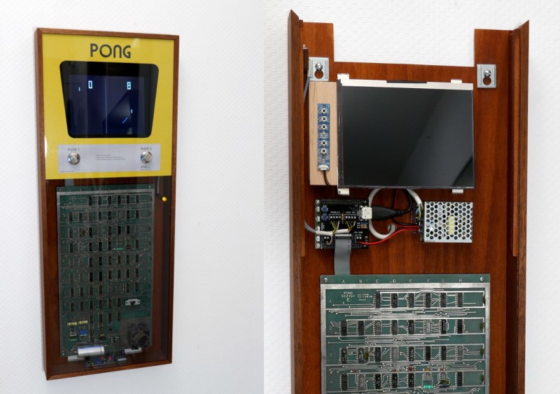
How cool would it have been if arcade cabinets had acrylic panels all along that let you gaze upon the field of TTL chips within? When [Jürgen Müller] scored the innards of an original 1972 PONG machine, that’s exactly what the plan was: build a suitable cabinet that re-imagines PONG as a sleek and stunning work of art.
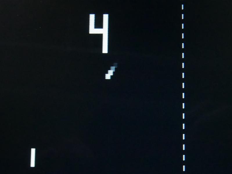 Instead of trying to cram a CRT in that nice mahogany cabinet, [Jürgen] opted to use an 8″ TFT screen. But get this: [Jürgen] built a Spartan 6 FPGA-based upscaler to adds the scan lines, blur, and afterglow that make it look like the classic PONG experience.
[Jürgen] also built an interface board that amplifies the sound, splits the video out into sync and brightness for the upscaler, and provides 5 V to the PONG circuit board. [Jürgen] decided to circumvent the board’s native voltage regulator in the name of keeping things cool.
[Jürgen] says the project’s web page is in a preliminary stage right now with more information to come. We sure hope that includes a video of it in action. For now, you can check out the files for the interface PCB, the FPGA board, and a list of the fonts.
Should you ever get tired of classic PONG, try playing it in one dimension.
Thanks for the tip, [Anonymous].


Preserving history and interactive art, sweet!
Nicely done!
How tall are the paddle knobs? My perspective is probably off, but they look very shallow in the photos. I mistook them for buttons, initially.
Thanks!
The knobs are “top hat” shaped, like the ones found on many guitars, but all metal. Reasonably close to what was used on the original PONG game, although not perfect. (They should be matte-anodized aluminum, it seems, but I only could get chromed ones.) But nicely playable.
For a good time, goggle for “1972 pong arcade schematic”. Omg, how did anyone even begin to conceive that circuit? If you wanted to build your own, say, 6502 out of MSI, you’d probably have a clue how to begin – lash some counters and registers together with some timing and control, etc. But this thing! It’s simultaneously the embodiment of software and video generation in the same circuit! Not only that, I saw at least three 555s in there in just a quick look.
Yeah, definitely preserve that board, and display it, that thing is a Monument.
Yes, it’s a pretty clever design! The video generation and game logic are one and the same. There is no “screen buffer” memory, which would have been far too expensive. Instead, various counters keep track of where the ball and paddles are, what screen line and column the video output scan is current looking at, and whether it’s time to switch that electron beam on or off.
Which is why I wanted the board framed behind acrylic rather than hidden away in a cabinet. ;-)
I am very interested in the FPGA emulation of an old-time CRT display. Would like to hook up a terminal emulator to it. Bookmarked.
Designing one of these in SSI/MSI is a closed book to me now as much as it was then, but “the great equalizer” came in with the AY-3-8500 “Pong chip”. Anyone with wires and pliers could build a TV game with one! I remember it well because it was one of the first projects that I ever built that actually worked the first time that I turned it on.
I actually worked for General Instrument when we developed the pong chip.
Shutup and take my money