Traditionally, 3D printer control boards have used simplistic 8-bit microcontrollers to command the stepper drivers and ultimately move the machine where it needs to go. Newer boards have switched over to 32-bit microcontrollers, but they’re still relatively limited computationally. Because of this, a Raspberry Pi running OctoPrint is usually used to provide more complex features such as remote management and live video.
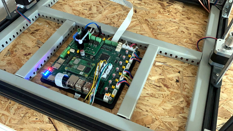
Looking to combine these different devices into a single all-in-one board, [pkElectronics] developed the Sigmoid S7P. With an STM32 microcontroller, TMC2209 stepper drivers, a Raspberry Pi Compute Module 4, and plenty of room for expansion, it promises to be a drop-in upgrade for essentially any 3D printer running on an open source firmware that could be ported over.
According to [pkElectronics], the idea for the Sigmoid had been floating around for several years, but never got off the ground due to the difficulties in dealing with the SO-DIMM interface used by previous iterations of the Compute Module. But with the switch to smaller and denser connector for the CM4, the board finally started to take shape.
Whether you just used it as a convenient way to integrate OctoPrint into your printer, or want to get into something more advanced like Klipper, the Sigmoid S7P looks like a very exciting project. [pkElectronics] says they are considering producing the board commercially if there’s interest, so if you want one of these for your own custom 3D printer build, let them know.


Kind of a rough name, eh?
I personally prefer smoother names, yeah.
How about Coltrane, as in John Coltrane who presumably said smooth quite a lot while playing jazz.
Pun intended?
Pun? What pun? I have no idea what you are talking about your honor. I simply for no particular reason felt compelled to comment on the roughness/smoothieness of the project’s name. Objection dismissed!
would you prefer ReLU instead?
One big issue with the compute module, is how it’s just way too expensive compared to the Pi Zero…
For Smoothieboard v2 we asked users if they wanted a CM4 port, or a Pi Zero port, and they universally wanted the Pi Zero port.
Which you understand when you look at the price of each, the Pi Zero starts at €5, the CM4 at something like €30….
As a company, we can’t bulk-buy the Pi Zero and sell it *with* the Smoothieboard as a bundle, we wouldn’t get the €5 pirce-point if we did that, that price is limited to single-unit purchases by end users.
However, it doesn’t matter, it’s trivial enough for our users to just separately get a Pi Zero and plug it into the Smoothieboard. And it’s MUCH cheaper for them. If we sold boards with the CM4 on it, we’d have to add our margin to that, for the end user it’d end up at something like minimum 50€ to have a Pi attached to their board, which is 10 TIMES more than them getting a Pi Zero…
It just doesn’t add up…
The only downside with the Pi Zero is the CPU is really quite old now and can’t really cope with things like running a camera + octoprint. Also because of the the way the WiFI was implemented on the Zero-W it uses a lot of CPU cycles when streaming any significant amount of data (e.g webcam streaming). Overall I think a compute module 4 running octoprint + klipper in this way is an idea solution. Sure it might not be the cheapest but theres nothing stopping you using a seprate controller + RPi, this project is clearly about integration and convenience.
Users needing more power than the zero can provide are going to use “normal” raspis.
I do agree having everything integrated is convenient, it’s the reason for the idea of stacking the pi zero on the smoothieboard in a very similar way to what is done here.
Maybe this system will be surprisingly popular and the other systems will imitate it in the future, who knows. We’ll keep our eyes open for this sort of stuff.
Well the CM is substantially cheaper than the equivalent pi (assuming both need the smoothie or equivalent secondary board, as that is where the CM’s actually add cost), and its much much easier to provide cooling for, which in a 3d printer full of other hot electronics might really matter.
Sure its pricer than a zero, but then its performance and capabilities are massively different, so its all down to how you plan to use the computer bolted to your printer, and if the zero has even close to enough grunt, which personally I’d say it really does, but then I don’t care for pretty pictures or streaming, just getting the job done….
Sure, the issue is on something like a Smoothieboard, the intended use is as an octoprint host, and unless you want to use a webcam, the pi zero is enough to do octopi, so going for a more powerful pi is not required, thus the popularity of the zero in that specific context.
Gina Heußge, head developer of Ocroprint clearly recommends against using Zeroes to run octopi.
I personally tried it, and it didn’t work. I never used video.
Octopi runs like crap on a Zero.
It works (in the most basic, click-and-wait-for-a-response form of “works”), and I’ve used it on one myself, but it’s such hot garbage that the print stalls when you load the UI to check status.
It is woefully inadequate for the job unless treated it very gently.
I’d expect the developer of one of the more expensive consumer-oriented 3D printer boards to choose hardware that doesn’t inherently suck for the role.
Meanwhile, even the now-outdated Pi3 is snappy in its responses when loaded down heavy with plugins.
Thanks for your thoughts and comments.
As Sebastian pointed out, this was primarily about building something as integrated as possible. Of course there are cheaper ways of achieving the same or similar functionality, but the price of this as a potential sales product was not a design criterion.
It´s a complete overkill, I know. This is something you get because you want it, not because you really need it, but this applies to many things in life. In the end, it works and I had lots of fun building it, which means it already served it´s purpose.
There’s definitely a lot of value to designing something without caring for price, it tends to be how breakthrough happen. I’m curious what people will do with this and how well it’ll do, will be keeping an eye.
There are tasks for which total price is not the prime driver.
As an example, I’m aware of one proprietary robotics development project that’s making heavy use of on-board kubernetes to manage the local cluster of CM4-based systems. I’m not sure I would have made all the decisions they did, but it does give them an extremely powerful ability to rapidly deploy the appropriate platform, navigation, control, and payload hardware and software configurations. Given that they have strong requirements for whole-of-deployment verification, it’s a good trade-off for them.
In projects closer to home for me, a pi4 would be far more suitable than a pi zero, except that, if the expense of a backplate is justifiable, the cm4 offers much more flexibility and more high performance IO options. I’m also more confident in deploying a cm4 in a wider range of temperatures for 10 years.
Oh for sure, I was just talking about the extremely specific domain of CNC controllers
Well done on the build. That looks nice.
Seems like vast overkill for running the printer’s steppers. Although I guess people frequently computer front-end the printers anyway, so I get the point.
It’d be nice to see a tailored interface on 300~400mHz general purpose-ish hardware. This made me realize I haven’t looked in a few years… are any firmwares aquireing OS features?
Things are getting more and more sophisticated. There are trends to move the motion control algorithms to the raspberry pi (e.g. Klipper) and use the MCU as a highend IO expansion. But other firmwares still try to run all of this on the mcu itself and use the RPi as some kind of HMI device.
Especially if you move away from simple cartesian kinematics things need a bit more of crunching power or if you go for something like active resonance cancellation then you need more than a small 8bit AVR mcu.
Klipper is for 3D printing and is slowing expanding. Remora started in 2017 running LinuxCNC on the rPi and while it initially was setup on a 3DP, it’s LinuxCNC so it’ll run routers, milling machines, plasma cutters etc.
Klipper and Remora are the only two projects I’ve run across doing this. ie stepgen stuff on the 3DP controller and motion planning and everything else on the rPi.
https://remora-docs.readthedocs.io/en/latest/intro/intro.html
It’s not well known, but Smoothieboard is separating planning from step generation for the “pro” version of the Smoothieboard v2 (v2-pro) which will use a FPGA for step generation.
Planning still occurs on a microcontroller (not a processor like the pi), but the chip is quite the upgrade, and it’s so powerful it’s getting pretty close to what the pi has. Also, it will not be doing anything the pi is not doing. So while it’s not actually using a Pi, it might as well be, functionally.
This is meant as a first step towards moving Smoothie, potentially, for v3 (this is not decided, where we go will depend on testing of the FPGA work), to a processor + FPGA architecture, which would be very similar to what Klipper does (except way more powerful, because FPGA…)
Remora is using LPC1768 and LPC1769 boards now so current Smoothieboards would work. The alternative to running LinuxCNC with Remora is to use a MESA card which is an FPGA but I have little doubt you already know this. It’s just so great to have all these options without having to rob a bank.
I’m intrigued by your vision of putting an FPGA on the 3DP controller and stepping up the ARM processor capabilities. Going to give you some nice fast stepgen side and more leg room for motion planning, etc on the ARM side.
I’m not very conversant at LinuxCNC but if you talk to those who are, there’s almost nothing it can’t be made to do. That seems to be a big benefit of that setup, ie a few config files and it’s running a completely different machine and different class of machine too.
Keep pushing the envelope.
> but I have little doubt you already know this.
I’ve actually just learned about Remora for the first time in this thread. I’ll be taking a closer look at it a bit later.
> Going to give you some nice fast stepgen side and more leg room for motion planning, etc on the ARM side.
Yes, there is some logic to using the best tool possible for the step generation (FPGA), and the best tool possible for all of the non-real-time stuff (an actual processor). Smoothie v2 is working on progressively going in that direction, the first step will be on v2-prime on which we have a co-processor that will handle step generation while the main core will handle the rest, so it’ll essentially be what we are talking about here, except not using specialized tools. But once we have that working, moving everything to those specialized tools will be much easier.
That’s fantastic. 10 years ago did you ever think you’d be looking at doing FPGA on consumer/maker grade hardware?
It’s a good time to be doing hardware.
> That’s fantastic. 10 years ago did you ever think you’d be looking at doing FPGA on consumer/maker grade hardware?
10 years ago (about a year before I started writing Smoothie’s code), I didn’t know what a FPGA was :) The Internet is amazing at enabling us to learn and make progress.
Having already done a few research projects on a FPGA I actually looked into this as well.
But when observing the MCU load in the Klipper Firmware, I came to the conclusion that it simply wouldn´t be worth the hassle. I´m currently doing test prints with a core-xy somewhere between 100 and 150mm/s and a 64 microstepping and it barely reaches 4%.
So there´s still a huge amount of crunching power unused and a STM32F4 isn´t even close to a high performance mcu. Also Klipper does close to no hardware specific optimization so there´s also a lot of potential left unused.
If you want to switch from steppers to raw bldc motors with position encoders and do the block commutation and motion control all on the smoothieboard, than I´d be with you to opt for an fpga.
What I believe is far more promising is the modularization approach introduced with the recent development of toolhead boards like the duet 1lc or the huvud. I believe with a bit of ingenuity and a few wise design decisions one could get completely rid of a monolithic control board and simply put everything on small can bus nodes. Just a Pi with a CAN transceiver as a master and all other functions distributed on smaller io units.
> I came to the conclusion that it simply wouldn´t be worth the hassle
The thing is it’s not just about maximum step rates. It’s about quality of step generation, of acceleration curves, about how complex the math you’ll do is (nth order etc). One thing the FPGA will allow us to have is an independent clock for each axis, instead of all of them sharing it and having to step on the same clock tick. It’s a lot of little things like that, that can be improved. On a laser cutter, you also need to handle data at pretty high rates when you engrave. Some machines (deltas) have the math stuff going on, with which current machines take shortcuts, but a FPGA-based machine wouldn’t need to.
All in all, there is indeed a lot of room for improvement/exploration already without a FPGA, indeed. Smoothie v2 will use a STM32H7, which is *way way way* more powerful than the LPC1769. But we still are working on having the FPGA on the v2-pro.
About a fully modular structure, the issue with that is that no matter how you spin that around, with today’s hardware when you do the accounting, it’s still way more expensive than a monolythic design, for minimal rewards. That might change in the future, and when it does you can be certain lots of people will jump on the opportunity and make that happen. But over the past decades there have been a lot of attempts at a fully modular system like you describe, and none of them have take off. That’s no coincidence.
Having a FPGA at hand is always a cool feat. nothing to argue about that.
Regarding pulse clocks per axis, even with the FPGA in place you would still be running at some fundamental frequency which might be pretty high, but still the common baseline for all other clocks derived from this. So I believe something similar could be achieved on an MCU, not with the same precision as on a FPGA running with a baseline clock in the GHz range but at least to a certain degree.
The complexity of the maths involved in motion control or with acceleration smoothing should have a certain upper boundary where it becomes useless to compute it with even more precision. It´s still a mechanical system which has to obey a few fundamental laws of physics if it want´s to move around. Same applies for the laser stuff, streaming a high resolution image to the laser while moving at several hundred mm per second is fast somehow but not in the range of gigabits per second.
I actually don´t know where this boundary exactly lies so it would be interesting to find out once you got your fpga board out.
I agree with you that going full modular is pretty hard, that´s what I meant with ingenuity, you have to figure out something really smart to get this going. Getting a MCU and a CAN transceiver for every single endstop is indeed going to cost a fortune without offering something useful. On the other hand, adding this functionality to a SSR might actually make sense. I think I´ll keep on designing stuff like this just out of curiosity.
In fact, I´d be really happy if we could continue this discussion as it´s a really interesting topic with lots of different aspects. But maybe in another place like discord, if you like just write me a message -> pkElectronics#5806
wolf.arthur@gmail.com
“Seems like vast overkill for running the printer’s steppers”
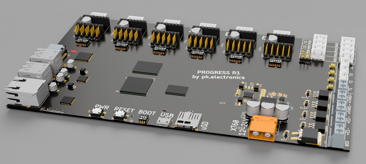
I have to admit the compact form-factor looks better than the version our group made. However, the major constraints we encountered were the power-trace minimum-width, and connector current limits. Even with 2oz copper, the supply traces in this projects board are likely too small to reasonably handle most NEMA17 sized motors, and with a 0.5mm pin pitch for that mcu it is likely a 1oz board (ridiculously wide conductor area would be needed).
example: 7 steppers * 1.7A per phase * 2 phases = 23.8A continuous draw with all drive-phases on.
Additionally, those wire-to-board terminal blocks look like they are sized around 15A. A possible problem unless they are splitting the supply across several conductors. They probably have already thought about this, but recall even the classic RAMPS 1.4 PCB had heating issues due to the production PCB use of thermal relief pads.
The smoothieboard is actually fairly well designed, and are worth the time to learn. I often recommend their teams project, as building our clubs through-hole PCB is 80% less fun. ;-)
Cheers,
J
Hi, thanks for your thoughts.
I considered the current handling capabilities of the PCB during the design phase, actually the supply traces to the steppers are pretty beefy and routed as careful as possible. From what I know about principles of stepper motor operation, the phase currents don´t actually add up this way as they run as two phase shifted sinuses you don´t get to the point of I_tot = 2 * I_phase. But you are right, this has to be observed carefully during operation and is certainly not optimized enough at this point.
The terminal blocks are indeed rated for 30A not 15 as you stated, the power distribution board with the mosfet switches is made with 2oz. copper for the prototype, but adding more to it was something I already thought about. The whole mainboard with the stepper drivers has a 15A car fuse in place so this basically poses the upper limit of overall motor current atm.
That part seems much smaller than the 30A 7.62 mm pitch Amphenol-Anytek 20020705-M021B01LF we used for our FET outputs.
The amount of board space your team saved with the smaller terminals is pretty impressive. ;-)
Cheers,
J
There are different terminal blocks in place for different purposes.
Main supply and bed output are 7,62mm 30A, extruder outputs are 5.08mm 14A both from wuerth elektronik.
The powererboard actually gets a redesign at the moment as I came up with an even better connector layout to make it easily replaceable as a whole unit.
The controller I’m working on seems like it fits your description: https://reprap.org/forum/read.php?2,885262 :) The SDK for ESP chips, ESP-IDF, provides some POSIX APIs for file access, networking, threading, etc.
Not for me. My 3D printers already have a control board which is adequate, and it was trivial to add a Raspberry Pi running Octoprint. I’m currently using a 3B+ and there’s no reason to “upgrade” to a Pi 4.
On the printer itself the print head has to move at a glacial pace compared to the processing speed of even the slowest 8-bit micro, plus all of the work has already been done by the slicer. What exactly am I paying for here?
On some printer designs, in particular some of the non linear ones, there is enough algorithmic complexity decoding the gcode file that an 8 bit 16Mhz vs 32bit faster micro can have a noticeable improvement in print quality.
Maybe not enough to saturate several hundred Mhz, but this way you know you have some room to spare.
Pretty board, but when it comes to SMC hardware interfaces, I prefer the USB only interface. SCB–USB–uC+IO.
There is one simple reason for it: the SBC environment is a fast changing environment. On the IO hardware side you want something with some longevity, so tying it to one product, from one supplier that is fast changing is not ideal. With USB only interconnection, any SBC system can be used. You remain compatible with future cheaper, faster, more available systems. As a super bonus, you can do your development on your PC or laptop, the “universal” part of USB is the key.
I love this idea…just wish it had plug-in stepper drivers….as I intend to switch to closed loop for X/Y/Z!
Other than that I would be seriously considering investing in this…It would certainly clean up my install!
Have a look at Remora firmware, It’s LinuxCNC on a rPi connected to stock 32bit controller and has encoder support for closed loop operation. There’s a testing branch for TMC stepper driver support too.
https://remora-docs.readthedocs.io/en/latest/intro/intro.html
I have been testing it for my cnc mill. Its a great solution for me as i was already familiar with the SKR1.4 boards and Raspberry pi’s. The developer is active and very helpful with not only configuration but also adding features for my machine.
Nice but why not put Remora firmware on an existing 32bit controller and use LinuxCNC on the rPi to control the machine over the SPI interface? LinuxCNC has been around for decades running industrial CNC machines but usually through a few hundred dollars worth of extra hardware and a fullsize PC but now a $40 rPi 4 and a $40 32bit controller will do the job.
https://remora-docs.readthedocs.io/en/latest/intro/intro.html
I just had a short look at the Remora docs but from what I saw it should be definitely possible to run it on my board.
SPI between the RPi and the MCU is in place on the board as RRF and Duet Web Control do it the same way.
I´m not really into CNC so I was unaware that this existed.
This reminds me of the duet 3, they recently switched to using a seperate rpi3/4 for the web interface instead of an esp8266.
One thing of interest on the duet 3 is the use of CAN-FD which is the newer can bus standard for faster data which can be used in a way similar to ethercat (but cheaper) for external motion control boards.
It’d be interesting to see if you could adapt the duet firmware for the S7P
I already did a proof of concept with the RepRap Firmware STM32 Port from Andy Gloomy and the DWC Web Interface.
Managed to get the communication between Pi and STM working but haven´t been running the printer with it yet.
I’d actually be hoping for a Pico powered board that offloads more complex instructions to a Pi CM4 if needed. With the help of Coral AI, I’d like to see if realtime offline print failure detection could be achieved. Print Nanny is doing this with no Coral module though.
here a similar project https://hackaday.io/project/166466-64-bit-3d-printer put marlin code into pi
Klipper would be perfect on this.
Difficulty with the SO-DIMM socket on Compute module 1-3? Why?
Not actually a difficulty, but rather a solution not as elegant as it is now.
The CM3 included way more GPIO than the CM4 which would have all gone unused in this project, also having the ethernet phy directly on the CM4 is pretty nice.
This project would of course have been possible with the CM3 but I just didn´t like it that way.
Remember, klipper and things like the AI spaghetti detector are just a few examples of things a bit more bleeding edge, added kinematics and machine vision can use more powerful computing
We think there will be HUGE commercial interest for this. Really hope this become available for everyone in the future.
We covered this story in this weeks episode of The Electromaker Show: https://youtu.be/SOVXHKhsLVI?t=304