Over the last year or so, we’ve been checking in on the progress [Andrew Consroe] has been making with his incredible CNC scroll saw project. While we were already impressed with his first prototype version, he somehow manages to keep pushing the envelope forward with each new upgrade, and we’re always excited when one of his progress reports hits the inbox.
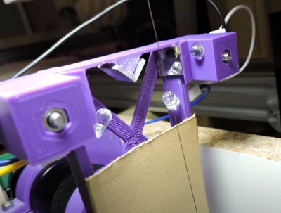
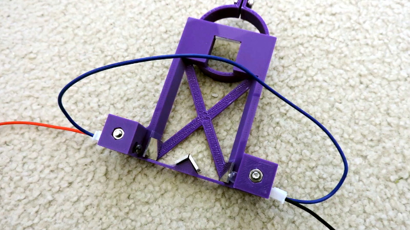
Recently he’s been struggling with the fact that the considerable flexing of the scroll saw’s ultra-thin blade introduces positional errors while cutting. To combat this, he’s developed an ingenious sensor that can track the movement of the blade in two dimensions without actually touching it. Utilizing the Raspberry Pi HQ camera, a 3D printed framework, and some precisely placed mirrors, [Andrew] says his optical sensor is able to determine the blade’s position to within 10 microns.
 In the video below [Andrew] goes over how his “Split Vision Periscope” works, complete with some ray traced simulations of what the Pi camera actually sees when it looks through the device. After experimenting with different lighting setups, the final optical configuration presents the camera with two different perspectives of the saw blade set on a black background. That makes it relatively easy to pick out the blade using computer vision, and turn that into positional information.
The periscope arrangement is particularly advantageous here as it allows the camera and lens to be placed under the work surface and well away from the actual cutting, though we’re interested in seeing how it fares against the dust and debris that will inevitably be produced as the saw cuts. While he hit all of his design goals, [Andrew] does note that his mirrors do leave some room for improvement; but considering he hand cut them out of old hard drive platters we think the results are more than acceptable.
An incredible amount of progress has been made since the first time we saw the CNC scroll saw, and we’re eager to see this new sensor fully integrated into the next version of [Andrew]’s impressive long-term project.


Next step, a closed loop controller with his sensor instructing a series of magnets to tug the blade back into line, with a similarly high level of precision. A bit like the magnetic alignment in the lens sled in an optical drive, but pulling on the blade itself. Hopefully a portion of the blade or at least it’s bearings should remain below it’s Curie temperature when in operation.
Why add all that extra complexity when he can already move the blade relative to the wood by just moving the wood more?
Having worked with scroll saws before, the problem usually isn’t the blade, it’s that you’re forcing the wood too hard. I’d say rather than try to force the blade back into shape, it’d be an indication to back off the feed rate.
I’m surprised he didn’t go with an interferometer, using the blade itself as a mirror.
Huh an interesting idea, I assume you mean using it as the end mirrors, not the middle one that would need to be half-silvered? Since he noticed that the reflectivity of the blade itself varied as it moved and twisted, wouldn’t that make it difficult to keep the focus tight enough to make sure the light made it all the way through the path? If it’s serving as the mirror at the end of the then you’d need to actually have an extra mirrors to bounce it back and hit the correct side of the blade which would seem to magnify any positioning error as well as introduce more noise (or at least signal loss from convoluted light paths to get too and from the laser & detector).
You may try a reflective tape bonded to the blade where the camera sees>>> Like the sort of stuff emergency reflectors are made, you can get it in a tape… just stick it on and the cam will always see it.
Anything stuck to the blade itself would be degraded pretty quickly as the blade cuts through material, likewise if it comes off at the wrong spot it might gum up the drive mechanisms
A Scroll saw uses a tiny fraction of the blade on the contact cut face.
As long as it is clear of the bite path and the blade does not get too hot..it will work good.
If you lamp the sticker from the cam it will return a sharp and high output signal for the scanner to use.
I save the extra bits of sticker i get for the license plate… It uses that 3M 6000% reflective stuff… it would be perfect, wrapped around the blade spine it can be attached to all the scroll you have/ It can b placed in just the right spot to really hype the accuracy.
You can also buy a shaker pen with the 6000% paint in it, they are a bit expensive… but they would be ideal to paint the visual part of the blade. it would also work on the spiral blades.
Think like the stop sign at night… in your headlamps it blazes really bright..
Just a dot of paint on the blade can give you enough of a target to use.
If you use 3M paint you can put just a DOT of it on the spot you will watch, one LED and you are done.
If you flash the LED you can even determine twist.
As he showed, the blade is both moving and twisting around. You’d have to account for both.
You’d think you might be able to come up with at least a heuristic to determine the blade’s behavior as it’s being pushed through the wood. The tricky bit is to figure out when the blade is cutting through wood vs. when is it retracing its path through a cut (but since you know the path where the blade has been, you should be able to figure this out too).
Regarding using a camera as a sensor, there is the issue of latency. On some sensors, you can get a faster rate if you cut down the area of the image you’re capturing. But in some instances, you might be better off using a lateral effect photodiode, assuming you can get a bright spot image against a dark background. Then the latency drops to almost nothing, and no image processing is required either. Of course, in this case, he’d either need two of them, or he’d have to find a way to multiplex one of them (by alternating light sources).
> You’d think you might be able to come up with at least a heuristic to determine the blade’s behavior as it’s being pushed through the wood.
Until you hit knot or denser patch of wood.
> But in some instances, you might be better off using a lateral effect photodiode
Or laser scanner like for barcodes, with timer reading when blade interrupts beam.
The saw isn’t just for cutting wood, so it would need to be calibrated for all sorts of materials. In this case, the blade lag was showing up even when cutting foam.
Is it going to be hard to keep sawdust out of the optics?
Air assist?
Flatbed scanners are a good source for first surface mirrors like these. https://hosting.photobucket.com/images/i382/Comedicles/FSMirrors.jpg