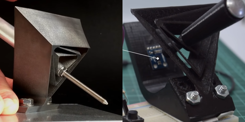
One of the many advancements brought about by 3D printing is the rapid development of compliant mechanisms and flexure joints. One such example is [jicerr]’s joystick, which uses a pair of spherical flexure joints recently developed by researchers from Delft University of Technology in the Netherlands, See the videos after the break.
Both flexure joint designs make use of tetrahedron-shaped elements, allowing an object to pivot around a fixed point in space like a ball-and-socket joint. One of the joints, named Tetra 2, is perfect for printing on a standard FDM printer, and the 3D files were uploaded to Thingiverse by [Jelle_Rommers], one of the researchers. [jicerr] took the design and created a base to mount an HMC5883 3-axis magnetometer a short distance from the focal point, which senses the rotation of a small magnet at the focal point. An Arduino takes the output from the magnetometer, does the necessary calculation, and interfaces to a PC as a joystick. Demonstrates this by using it to rotate and pan the design in Solidworks. One thing to keep in mind with this design is that it needs a fixed base to prevent it from moving around. It should also be possible to integrate the design directly into the housing of a controller.
Another amusing application is to turn it into a pen holder with a chicken head on the front, as demonstrated by [50Pro]. If you have any ideas for other applications, drop them in the comments.
Compliant mechanisms have a number of interesting applications, including harmonic drives, dial indicators and thrust vectoring mounts.
Thanks for the tip [Keith Olson]!


Is there a nuts and bolts version of this, or is this some very special FEM modeled thing that needs to be done just so?
For nuts & bolts, there is already the gimbal. If you want to duplicate this shape, though, I expect you could do it with angle brackets and plastic sheet material.
A gimbal isn’t quite the same because this projects the point of rotation out into space in front of the device, not in the middle of a ball cage.
I guess it could be done. Only trick is that axes of all hinges must pass trough the same point. If you take few trapezoids and connect them with some hinges, it should work.
This is freaking BRILLIANT
For the love of god someone please adapt this to replace the N64 cup/retainer design
Now that looks like black magic!
This! It’s jaw-dropping to watch it move.
If you get the nuts and bolts to flex in the right ways, I suppose…
Flexure joints rely on flexing of things. See Wikipedia [1] on why and when they are a good choice.
[1] https://en.wikipedia.org/wiki/Flexure
What about a 3D printed 3D mouse for CAD?
Yeah was thinking about that as well. trying to figure out a flexure design which would allow enough movement in all directions. would be a good idea to throw 3d connexion of their “near monopoly throne” if you market it to hobbyists. and sice using a flexure would simplify the mechanics you could make it cheaper potentially.
The difficulty would be to persuade CAD software developers to support the new 3D mouse or one would need to write a clone of the 3Dconnexion drivers. (The license on the 3dconnexion drivers is of course limited to their hardware.)
It’s easier to just buy a used official unit.
Can´t see what the problem is. Just make the hardware compatible to any of those existing and supported 3D mice. No need to persuade anybody or reinvent the wheel.
The problem is that most CAD software communicates with the mice through proprietary 3dconnexion drivers that provide a higher level interface than the USB HID provided by the hardware. It’s easy to make thardware compatible, but just plugging it in won’t work unless you use the 3dx drivers. And the drivers have restrictive licenses.
I made a USB adapter for one of the old serial 3D mice (based on an stm32f1), so I know it’s easy to duplicate the USB interface, but I only use the adapter with one of the branded 3d mice, not to violate the driver license.
You don’t need to write a clone of the 3Dconnexion drivers, it’s already here: http://spacenav.sourceforge.net/
And, you don’t need to “persuade CAD developers” to anything if you’re using FreeCAD — you can just add it in yourself. That’s what the spacenavd folks did.
This is why free software.
Fair enough: if you’re using Linux, you can use this. And if you’re using open source CAD software, you can write your own support. So the problem is only for Windows-only closed source CAD software, and for web based things like OnShape, which use a 3dconnexion bridge server between the web and the mice (unless spacenavd supports the bridge protocol).
I wonder if this could be used for a gimbal design in reverse… I’m trying to create a pan tilt mechanism that uses only 45° of rotation from a single motor, spliting the 90° rotation into 2 axis… Bears further investigation
Glad you found it interesting!
I uploaded another application a few days back…a sort of “micromanupulation device” using the same concept, I leave it here:
https://youtu.be/5olxACvCclg
I bet it would make a good suspension/shock absorbing mount. If you get the math right you could tune the suspension using variable thickness walls in precise areas to hold certain weights or adjust stiffness.