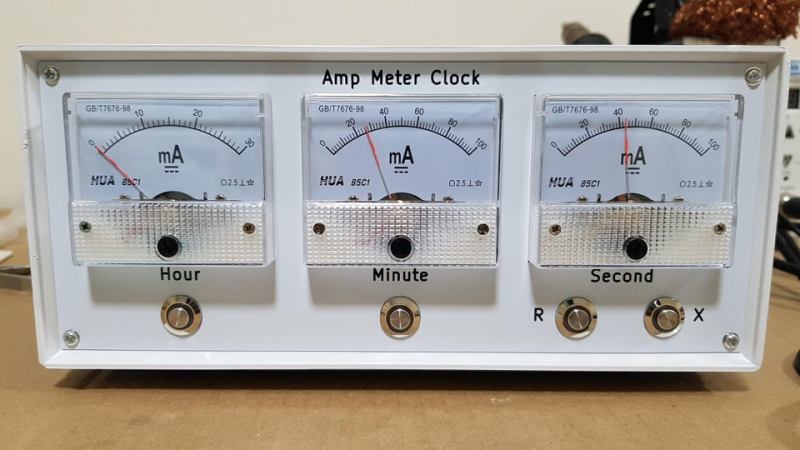
It is a rite of passage for hackers to make a clock out of traditionally not-clock items. Whether it be blinking LEDs or servos to move the hands, we have all crafted our own ways of knowing when it currently is. [SIrawit] takes a new approach to this, by using ammeters to tell the time.
The clock is built using mostly CMOS ICs. A CD4060 generates the 1HZ clock signal, which is then passed to parallel counters to keep track of the hours, minutes, and seconds. [SIrawit] decided to keep the ammeters functioning as intended, rather than replacing the internals and just keeping the needle and face. To convert the digital signal to a varying current, he used a series of MOSFETs connected in parallel to the low side of the ammeters, with different sizes of current-limiting resistors. By sizing these resistors properly, precise movement of the needle could be achieved by turning on or off the MOSFETs. You can see the schematics and learn more about how this is achieved on the project’s GitHub page (at the time of writing, the most recent commits are in the ‘pcb’ branch).
In addition to the custom PCB that holds all the electronics, PCBs help make up the case as well. While the main body of the case is made out of a repurposed junction box, [SIrawit] had a PCB on an aluminum substrate manufactured for the front panel. While the board has no actual traces or electrical significance, this makes for a cheap and easy way to get a precisely cut piece of aluminum for your projects, with a sharp-looking white solder mask to boot.
We love to see cool and unique ways to tell the time, such as using Nixie Tubes to spell out the time in binary!
[via r/electronics]


Hi Hackaday, Sorry, but this is not a “new approach”. I’m a long time reader and you’ve featured clocks using analog meters several times previously. https://hackaday.com/blog/?s=analog+meter+clock
New editor, I think. There are only a few articles going back less than a month from them.
The other ones appear to be voltage meters instead of amp meters. So internally it is a novel method even if the visual output is similar.
Analogue ammeters are no different than voltmeters – they just have a shunt resistor
You start with a meter that reads current. You use ohms law to calculate a resistor that will deflect the needle full scale at the maximum input voltage. For most accuracy, often not needed, you take into account the resistance of the meter winding.h
This is how “voltmeters” are made. Sometimes they put the series resistor inside the meter case other times the scale shows volts but you still need that resistor.
Like I said, fifty years ago people were suggesting cheap “tuning” meters intended for consumer electronics forthissort of readout. The first meter I had was a 1″ surplus tuning meter, 99 cents at Etco in 1971 or 72. Small, and cheaper than buying four bulbs and their sockets for a BCD readout.
You’re right, it’s a neat idea so fun to see people building cool stuff around what could be otherwise boring dial meters.
That’s not an Amp Meter Clock! – It’s an Amp-Hour clock :)
WATT ???
+1
Seems that this clock always has the current time.
(someone had to say it)
I wish I thought of that one! +1
Excellent job ! True there are a lot of “meter” clocks out there most use an Arduino or a Beagle and are code driven. Your’s is a refreshing build of a hardware driven clock. The mention of CMOS got my attention. Way to go !
There is a kit using an Arduino on Jameco.
https://www.jameco.com/z/ANGCLKV1-Wicked-Device-Angular-Clock-Kit-No-Soldering-Required-User-Programmable_2207831.html
No, it’s not a new thing.
Fifty years ago I got a book of hobby circuits from RCA, and it featured something digital that used meters for readouts. I can’t remember if it was a clock or something else.
I’ve never seen it, but I think there were high end products that used the scheme.
It wasn’t just in that RCA book. I’ve seen it in hobby magazines. Before LED readouts, maybe before Nixie tubes got “cheap”, digital projects “often” used a bcd readout, 4 lamps displaying 1-2-4-8. No decoder heeded, no expensive display. But it was a time of small but cheap meters intended for consumer electronics, and they made for an alternative display. Just some weighted resistors, and some vague markings on the meter.
I’m sure I mentioned this the last time this came up.
RCA solid-state hobby circuits manual, 1970 edition.
Circuit No. 9, “Meter Display” (p.92ff)
https://worldradiohistory.com/Archive-Hobbyist-Specials/RCA-Hobby-Circuit-Manual-1970.pdf
Wow! I actually still have a copy of the next version of that book (HM-92 instead of HM-91). Had a lot of fun with it when I was in high school. :-)
I got it in elementary school,between grade 5 and 6. As I recall, it was fairly cheap, RCA maybe treated it like an application book. I had a couple of books about ham radio by then, but it was probably my first hobby electronic book I owned (I’d read some out of the library). Somebody borrowed it to build an intercom in school, as I recall the school paid for the parts (and I can’t remember if it was ever finished).
I still have my copy, I think the front cover came off. That happened a lot with hobby books and magazines.
Looks like the initial call-out was deleted by the mods, I wonder why they did that while not also editing the article claiming that this was new https://hackaday.com/blog/?s=analog+meter+clock
A guy in our hackerspace built one, a few years ago…
https://wiki.logre.eu/index.php/LogClock_%26_Cuckoo
To the above…
Yes, ammeter clocks have been done before. Nearly all of them use PWM from a microcontroller. One uses a DAC chip and a microcontroller.
This uses discrete logic ICs for the RTC itself and a homebrew DAC made from discrete resistors and MOSFETs. No PWM, no microcontroller, no off-the-shelf DACs or RTCs, the ammeters are in stock condition.
I think there is genuine originality in this clock’s implementation, and I think kudos for its creator are in order.
It’s a hack!
Except as I pointed out, it was done before microprocessirs.
At least this guy didn’t tear apart some antique meters and replace their innards with servos.
Yes, the Hack-a-day readership remembers.
Shared Brain Technology some years ago sold a kit BOYE (Bring Your Own Enclosure) for such a clock. I got rather fancy stereo equipment case and built my own Chronulator.
https://www.flickr.com/photos/52062548@N00/2215037249/in/album-72157603783213194/
A cromulent Chronulator!
B^)