Analog Meter Clock Uses Parts From A Simpler Time

Clocks with hands that turn are all well and good for the common folk, but hacker types prefer something different. [Sjm4306] is one such person, and developed this analog dial clock with parts we’d almost consider retro by modern standards.

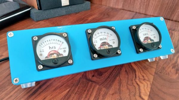
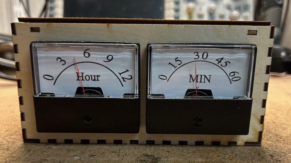
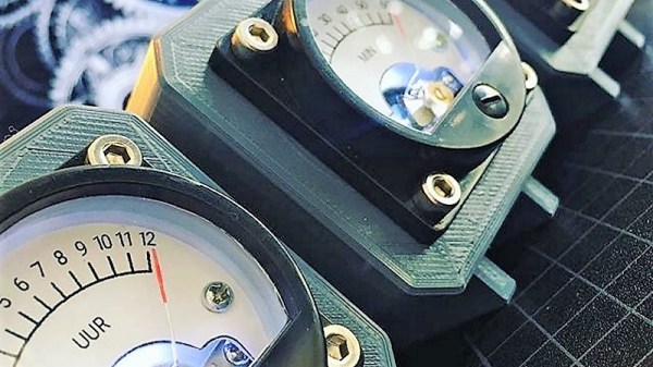
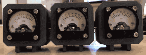
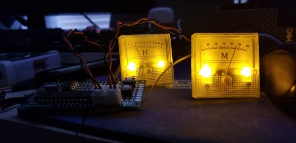
The microcontroller at the heart of the build is a PIC16F886. An 8-bit micro from the Microchip brand, it features no Arduino bootloader or USB interface, being flashed via a dedicated programmer. This is combined with a DS1302 real-time clock to keep accurate time, and a MCP4922 DAC which is responsible for generating the output to drive the dials. The dials themselves are sourced from eBay, being simple voltmeters. They’re given a new backing to display hours and minutes instead of volts, and backlit with LEDs for style.

In this day and age, we’re more used to seeing high-end micros used with integrated DACs and USB programming, but it’s nice to see the parts of yesteryear being used, too. It’s not the first clock we’ve seen from [sjm4306], either. Video after the break.

Continue reading “Analog Meter Clock Uses Parts From A Simpler Time”

Follow The Bouncing Needles Of This Analog Meter Clock

Our community never seems to tire of clock builds. There are seemingly infinite ways to mark the passage of time, and finding unique ways to display it is endlessly fascinating.

There’s something about this analog voltmeter clock that really seems to have caught on with the Redditors who commented on the r/DIY thread where we first spotted this. [ElegantAlchemist]’s design is very simple – just a trio of moving coil meters with nice industrial-looking bezels. The meters were wired for 300 volts AC, so the rectifier and smoothing cap were removed and the series resistance was substituted for one more appropriate for the 0-5VDC range needed for the project. New dial faces showing hours, minutes and seconds were whipped up in Corel Draw, and everything was put into a sturdy and colorful aluminum “stomp box” normally used for effects pedals. An Arduino Nano and an RTC drive the meters with a nice, bouncy action. Simple, cheap to build, and a real crowd pleaser.

The observant reader will note a similarity to a clock we covered a while back. That one chose 3D-printed cases for an airplane instrument cluster look. We like the spare case design in [ElegantAlchemist]’s build, but wonder how this clock would look in a fine wood case.

Educational Arduino Clock Uses Analog Meters For Display

When it comes to educational electronic projects, it’s hard to go past building a clock. You learn tons about everything from circuit concepts and assembly skills to insights about the very nature of time itself. And you get a clock at the end of it! [hamblin.joe] wanted to do a simple project for kids along these lines, so whipped up a neat design using analog meters to display the time.

The build relies on that old stalwart, the Arduino Uno, to run the show. It’s hooked up to a DS3231 real-time clock module so it can keep accurate time for long periods, as is befitting a clock. Displaying the time is done via the use of two analog meters, each fitted with a custom backing card. One displays hours, the other, minutes. The analog meters are simply driven by the PWM outputs of the Arduino.

It’s not a hugely complex project, but it teaches so much. It provides an opportunity to educate the builders about real-time clocks, microcontroller programming, and even the concepts behind pulse width modulation. To say nothing of the physical skills, like learning to solder or how to assemble the laser-cut enclosure. Ultimately, it looks like a really great way for [hamblin.joe] and his students to dive into the world of modern electronics.

Analog Meters Become A Clock For Father’s Day

Around Father’s Day each year, we usually see a small spate of dad-oriented projects. Some are projects by dads or granddads for the kids, while others are gifts for the big guy. This analog meter clock fits the latter category, with the extra bonus of recognizing and honoring the influence [Micheal Teeuw]’s father had on him with all things technological.

[Michael] had been mulling over a voltmeter clock, where hours, minutes and seconds are displayed on moving coil meters, for a while.  A trio of analog meters from Ali Express would lend just the right look to the project, but being 200-volt AC meters, they required a little modification. [Michael] removed the rectifying diode and filtering capacitor inside the movement, and replaced the current-limiting resistor with a smaller value to get 5 volts full-range deflection on the meters. Adobe Illustrator helped with replacing the original scales with time scales, and LEDs were added to the meters for backlighting. A TinyRTC keeps time and generates the three PWM signals to drive the meters. Each meter is mounted in its own 3D-printed case, the three of which are linked together into one sleek console. We love the look, which reminds us of an instrument cluster in an airplane cockpit.

Bravo to [Michael’s Dad] for getting his son into the tinkering arts, and cheers to [Michael] on the nice build. We like seeing new uses for old meters, like these server performance monitoring meters.

[via r/DIY]

Synesthetic Clock Doesn’t Require Synesthesia

We often think of synesthetes as those people who associate say, colors with numbers. But the phenomenon can occur with any of the senses. Simply put, when one sense is activated, synesthesia causes one to experience an unrelated, activated sense. Sounds trippy, no?

Thankfully, [Markus Opitz]’s synesthetic clock doesn’t require one to have synesthesia. It’s actually quite easy to read, we think. Can you tell what time it is in the image above? The only real requirement seems to be knowing the AM color from the PM color. The minute display cycles through blue, green, yellow, and red as the hour progresses.

Behind that pair of GC9a01 round displays lies an ESP32 and a real-time clock module. [Markus] couldn’t find a fillArc function, so instead he is drawing triangles whose ends lie outside the visible area. To calculate the size of the triangle, [Markus] is using the angle function tangent, so each minute has an angle of 6°.

[Markus] created a simple but attractive oak housing for the clock, but suggests anything from cardboard and plastic to a book. What’s the most interesting thing you’ve ever used for an enclosure? Let us know in the comments.

Do you appreciate a good analog clock when you see one? Here’s a clock that uses analog meters for its display.

A Clock Made Out Of Electromechanical Relays

Electromechanical circuits using relays are mostly a lost art these days, but sometimes you get people like [Aart] who can’t resist to turn a stack of clackity-clack relays into a functional design, like in this case a clock (article in Dutch, Google Translate).

It was made using components that [Aart] had come in possession of over the years, with each salvaged part requiring the usual removal of old solder, before being mounted on prototype boards. The resulting design uses the 1 Hz time signal from a Hörz DCF77 master clock which he set up to drive a clock network in his house, as he describes in a forum post at Circuits Online (also in Dutch).

The digital pulses from this time signal are used by the relay network to create the minutes and hours count, which are read out via a resistor ladder made using 0.1% resistors that drive two analog meters, one for the minutes and the other for the hours.

Sadly, [Aart] did not draw up a schematic yet, and there are a few issues he would like to resolve regarding the meter indicators that will be put in front of the analog dials. These currently have weird transitions between sections on the hour side, and the 59 – 00 transition on the minute dial happens in the middle of the scale. But as [Aart] says, this gives the meter its own character, which is an assessment that is hard to argue with.

Thanks to [Lucas] for the tip.

Bare-Metal STM32: Adding An Analog Touch With ADCs

An Analogue to Digital Converter (ADC) is at its core a straight-forward device: by measuring an analog voltage within a set range and converting the measured level to a digital value we can use this measurement value in our code. Through the use of embedded ADCs in microcontrollers we can address many essential use cases, ranging from measuring the setting on a potentiometer, to reading an analog output line on sensors, including the MCU’s internal temperature and voltage sensors.

The ADCs found in STM32 MCUs have a resolution between 12 to 16 bits, with the former being the most common type. An ADC can be configured to reduce this resolution, set a specific sampling speed, and set up a multi-mode configuration depending on the exact ADC peripheral. STM32 MCUs feature at least a single ADC peripheral, while some have multiple. In this article we will take a look at how to configure and use the basic features of the ADCs in STM32 MCUs, specifically the ADCs found in F0 and the ADC5_V1_1 type as found in most F3-family MCUs.

Continue reading “Bare-Metal STM32: Adding An Analog Touch With ADCs”