Call us old fashioned, but we feel like when you buy a piece of hardware, the thing should actually function. Now don’t get us wrong, like most of you, we’re willing to put up with the occasional dud so long as the price is right. But when something you just bought is so screwed up internally that there’s no chance it ever could have ever worked in the first place, that’s a very different story.
Unfortunately, that’s exactly what [Majenko] discovered when he tried out one of the USB-C power bank modules he recently ordered. The seemed to charge the battery well enough, but when he plugged a device into the USB output, he got nothing. We don’t mean just a low voltage either, probing with his meter, he became increasingly convinced that the 5 V pin on the module’s IP5306 chip literally wasn’t connected to anything.

Curious to know what had gone wrong, he removed all the components from the board and started sanding off the solder mask. With the copper exposed, his suspicions were confirmed. While they did route a trace from the chip to the via that would take the 5 V output the other side of the board, it wasn’t actually connected.
This is a pretty blatant bug to get left in the board, but to be fair, something similar has happened at least once or twice to pretty much everyone who’s ever designed their own PCB. Then again, those people didn’t leave said flaw in a commercially released module…
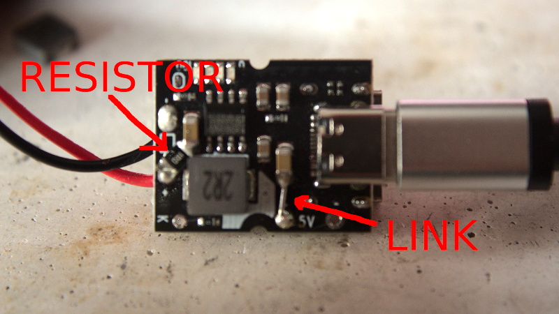
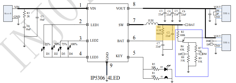
At any rate, [Majenko] just needed to solder a jumper on one of the non-sanded boards, and everything should be good to go. Well, not exactly. Adding a jumper got some power heading to the output side of the module, but only 3 V. Clearly, something else was wrong in the circuit. After some additional research and a few [BigClive] videos, he realized that some components were actually missing. Consulting the application schematic from the datasheet, it was clear that a capacitor and resistor had been left off. While the absent capacitor didn’t seem like it would be enough to cause the failure he was seeing, the resistor is supposed to be connected to the battery sense pin, and could explain why the chip wasn’t boosting the voltage.
With the resistor in place, the module started working as expected. [Majenko] notes that he still can’t get more than 1.5 amps out of these boards that are supposedly good for 2 A, but that’s another story entirely. With so many problems, it seems likely this module was a failed prototype and never meant to actually go on sale. But with part shortages ravaging the industry, it seems even the broken modules are getting pushed out the door.
Incidentally this isn’t the first time [Majenko] has tracked down some errant components in a supposedly turn-key board. Earlier this year he noticed that tweaking some of the parts used in the Raspberry Pi 4’s power supply helped reduce low-voltage warnings.


I can’t tell you how many low cost power related modules I’ve snagged off Amazon and turned out to be either straight garbage or hilariously so over spec’d that using as “intended” ends up in disappointment within a few cycles. It’s almost as if we must create our own if we want something to be useful within any semi-serious project at this point, or spend the extra money.
The general rule with any power pack or LED is to assume the true rating is about 10% of the claimed value. But I would expect it to actually work.
Poor manufacturing is not new. In the mid 1990’s we purchased some single use single outlet surge protectors. The power to the protected devices kept getting interrupted. On opening one, we found one cold soldered joint. We fixed them all, and kept using them. We tried to purchase more (great price) but they were no longer available from our supplier. “discontinued”. About a year later, we came in one morning to find nothing worked. The surge protectors had done their job – the inside of the cases were lined with “silver” and there were no components on the melted boards. All of the protected devices were just fine. There was one fax machine not protected – it was on lease and the responsibility of the leasing company. When the tech opened it, the case was lined with “silver” and the board was bare. We never did figure out what caused the surge, but we were glad we fixed the protectors. $50 worth of protectors vaporized instead of $7000 worth of computer equipment.
Sounds like a nearby lightning strike, if I were to guess.
Nearby?! Sounds like a direct hit to me. Someone annoyed Thor…
We were in the center of the 1st underground level under a very large mixed use complex (residential, retail, commercial). As we were building operations (maintenance, housekeeping, security) for the landlord, I am sure we would have heard if anyone else had a similar issue. I don’t see how a lightning strike could impact only our office. Lightning regularly hit the apartment tower (550′) and the office tower (350′) with no reported damage.
My latest was a telephone face tracking unit, a small pcb and a dc motor… then you pop your phone into the clip and it smoothly follows your face… super vool idea.
Out of the box… put 3 x AA cells in…and… nothing.
So popped the screws out and a quick look showed that the 3 battery connectors were not connected at all… 2 wires later and voilla a super cool face tracker…
Not bad for 7 euros…
Wait what?
7 euros where!?
Sauce please
I bought it in an online auction… vakantieveiling.nl
Retail price 49 95….
It is new and in tge box, only missing the battery connections.
Have fun!!
“But with part shortages ravaging the industry, it seems even the broken modules are getting pushed out the door.”
I don’t thing the parts shortages have anything to do with it. This was happening 3 years ago too.
Try 30+ years ago. Remember non-hipster Detroit?
How about Milwaukee – Harley Davidson had a 50% rework rate until the Davidsons took it back from the corporate Borg.
I ordered a usb to midi cable last year from ali and i could not get it to work. Opened it an the wires were spldered correctly. But the pads went nowhere. The unnamed blob did not even have loose traces. Of course gave some feedback to the chellers.
After getting annoyed with power supplies like this, I’ve decided to modify a 90W knockoff apple USB-C USB-PD charger into a variable voltage power supply. I have a broken one that I’m modifying and a working one I use as intended. It’s a quasi-resonant power supply design with a USB-PD chip on the secondary side of a transformer, and as such is well-suited to use as a variable supply for cheap. It’s poorly built, clearly had no QC, and there are solder globs everywhere, but it’s sure as hell faster than building one from scratch.
Looking at the sanded board i can tell you why he only gets 1.5A out of that board: the thermal relief spokes of some components are way too thin. Especially the left one on the pad for the first secondary filter cap. All the power delivered has to go throught that very thin spoke. Also the chocke spokes are too few or too small
I shall experiment with bypassing those with wire, but from the way it was behaving (a sudden drop not a gentle decline) my money is still on the inductor saturating.
These thermal spokes look normal to me. They are so short, that it’s OK for them to be that narrow.
Ummm… the output on those boards isn’t supposed to be the USB connector.
USB is for charging the battery, the output is on the two holes in the PCB labelled “5V”. Feel free to attach a USB connector there if you want to.
From the actual article:
Oops? Still, that’s an easy fix – a bit of wire from that pin (which also connects to the USB A on the other side of the board) and the 1206 capacitor just above it.
Think this is bad? @_mg_ (bad usb and the Omg cable dude)posted earlier today that 50% of the arduino nanos that he ordered with usb c connectors would not work because the cc lines were not connected ad were missing resistors. they would work if you used a micro cable with a micro to c adapter but otherwise its a complete fail…
This is the root cause. Make the product so cheap that people will not send it back even if it does not work. Please send this stuff back and people will stop selling inoperative junk. I know what you are thinking “it is not worth my aggravation”, but you are punishing the next customer as well by not putting these scammers out of business.
Sounds like old man Muntz is still doing well for himself.
I have bought a very similar modules on Ali. The board layout seems to be the same, only difference is that they are based on PB0063E made by Hotchip (sic!) instead of IP5306 and they work absolutely fine. The PCB has white silkscreening with letters “CKCS”, the +5V output is properly connected and no resistor needs to be added – the pin 6 (BAT) is connected directly to the positive terminal of the Li-Ion and the L1, as prescribed in the datasheet.
All in all, I am pretty happy with the module.
Does your module charge 4.35v lipo battery fully when the jumper is shorted
I too have bought a batch of boards from Aliexpress based on the Hotchip PB0063E and with the same identical PCB layout including fixes, however no CKCS marking. The first board worked as intended initially until I left it charging a 18650 overnight. In the morning no lights were lit on the board. Trying different USB-C chargers made no difference, it appears the board no longr draws a charge from the USB-C connector however with a charged 18650 and shorting the via marked K (pin 5) to GND, it outputs 5V on the output (one quick short turns on, two qukick shorts turn off the 5V output). I’m now on the second module which appears to work at least for now.