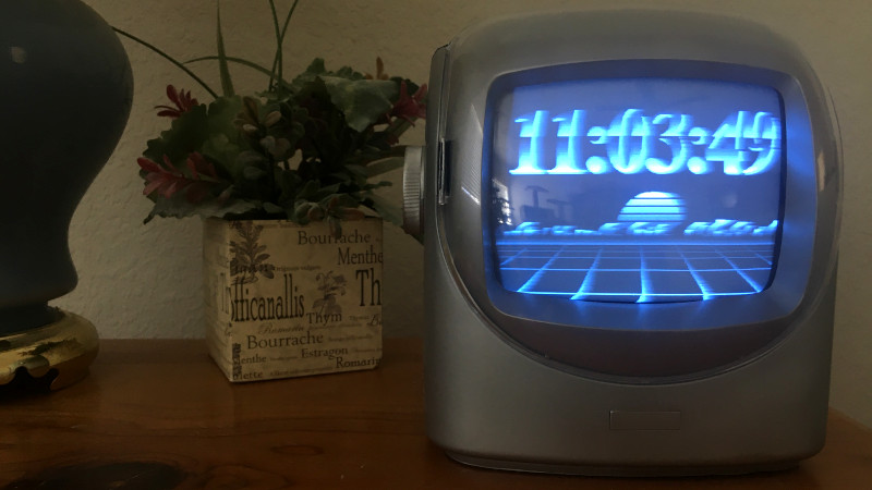
We’ve covered plenty of clocks powered by the ESP32, but this one from [Marcio Teixeira] is really something special. Rather than driving a traditional physical display, the microcontroller is instead generating a composite video signal of an animated digital clock. This could be fed into whatever device you wish, but given the 80’s synthwave style it’s pumping out, you’ll probably want to find a suitably retro CRT to do it justice.
 Specifically this is a variant of the “Dali” clock, where each digit seems to melt and morph into its successor. Though his version doesn’t necessarily share code with all the previous iterations, [Marcio] does credit the developers who have pulled off similar visual tricks going all the way back to 1979. Given the vintage of this particular animation, the neon skyline and infinite scrolling grid certainly feel like a perfect fit.
Want to add a little vaporwave vibe to your own workbench? Assuming you’ve already got a 80s style CRT, all you need is an ESP32 and two wires stuck into the composite video port. One goes to ground, and the other goes to the chip’s analog pin. Once everything is powered up, you’ll be able to configure the clock with a web-based interface. It doesn’t get much easier than that.
In the documentation, [Marcio] calls out a few open source projects which were instrumental to getting his clock off the ground. The pioneering work [bitluni] did to get video out of the ESP32 is something of a given, but he also sends a hat tip to [rossumur] for his collection of 8-bit game console emulators written for the microcontroller. Projects like this are a fantastic example of what’s possible when a community works together to truly push the envelope.


Awesome!!!!
This is magnificent! Thanks for the tip on composite out from the ESP32. It’s actually not bad at all. I’ve seen lower power micros do composite out, but the video output is typically compromised in some way.
24h clock FTW!
I’m a sucker for a CRT so I love it, now I need to hook it up to a modulator to send it to different rooms in the house.
Probably cheaper to just buy multiple ESP32 boards rather than a modulator that doesnt suck.
Not a great clock for those of us who can hear CRT tv’s
Alas, when you get older you may find yourself hearing that high tone whether there’s a physical source or not. Annoying, especially since I’m _not_ someone who abused his hearing as a kid.
I can still hear that @#$%! sound. It really hurts my ears and it hasn’t lessened with age.
Many big CRTs were very noisy at the 15Khz.
But i´ve some small Sony Colour CRT (9 & 15″) from a TV-Broadcaster who makes any noise.
Broadcasters would be very sensitive to such noise so they were made with higher quality parts. Unfortunately for me I worked in a computer lab (developing network services). I could find ‘bad’ monitors (and switching power supplies) by walking around the lab and finding the trouble makers. High frequency is very hard to home in on unless you are near it. BTW, I’m sensitive up to 19KHz (almost painful).
I can hear those and I like it. The 15kHz whine tells me that the TV is running. Which when I was young, was a good thing. Greetings from Pavlov.
Also hearing it is quite useful for fixing them. Within a quarter second you know if that trash picked (or customer repair job) TV is gonna work or blow up immediately and within a few seconds I know if there’s something amiss (working but potentially dangerous).
Next retro step: find an old B&W TV, and modify the video routines to do _subjective_ color. Yes, it’s possible; 6-frame cycle with three all black and then specific pixels lit in the next three depending on desired color. Works better on lines than on solid areas, but that’s just a graphic design issue. The flicker may be annoying, but an “impossible” color display is arguably worth it.
(I was attempting a C64/6502 implementation of this at one point, but I never quite got it working. In retrospect I think I know where the glitch in my assembler code was… Oh well. I no longer have a B&W CRT to justify the hack.)
Is that the one that only works with some types of phosphor?
I noticed one of my Dumb Terminals, when I scan my eyes across it, I get an almost DLP-like experience. The struck phosphor shines blue while the afterglow is yellow.
It should work with anything that’s basically close to white and can give enough contrast with the black. Early in the days of TV, someone tried spinning a subjective color wheel in front of a studio camera and the audience did see colors. 30FPS isn’t the ideal frequency, but it’s close enough to at least get some response.
Subjective color occurs because the eye responds to some colors faster than others, and by controlling the timing you can emphasize early or late responses. Note that the white background in the “live” side of the wheel seems to be important to the effect.
There’s an animatedversion of the wheel you can play with at https://michaelbach.de/ot/col-Benham/index.html … If you get the speed right you’ll see the rings become colored to at least some degree, red, green and blue. 360 rpm is roughly equivalent to what you could get with a six-TV-frame cycle.
I haven’t seen anyone do a real graphics engine that rendered as subjective color…. and as I say, you probably couldn’t do much more than lines with it — but I really liked the idea of having a b&w monitor display an error message in red, even if it had to flicker to do so, and It Ought To Be reasonable easy to try these days.
Awesome idea! I tried that webpage you shared and I could clearly see the red, a brownish yellow, and blue. I might have to try building a demo like that! The NTSC video out code is using a palette in memory, so it should be fairly simple to draw a complex image once and rapidly change a few palette entries to get the desired flashing frequency. This can be syncronized to the vsync to avoid tearing.
Was just playing with this other esp32 video library last night. https://github.com/Roger-random/ESP_8_BIT_composite/ – need to see if I can make it do pal 60 because 50hz is disgusting to look at and my oldest crts are not multisystem.
You could probably change the refresh rate by modifying this line https://github.com/marciot/esp32-dali-clock/blob/2654525cb78b490394deb3db94b6e6bd5be19311/src/gfx/CompositeColorOutput.h#L365 , but don’t ask me how since I don’t really know how the hardware works. Anyhow, thanks for the tip on Roger’s library. I’ll have to check out his code and see how it differs from mine, as we both started with ESP_8_BIT code as our base.
According to this wikipedia article, https://en.wikipedia.org/wiki/PAL, PAL 60 is basically NTSC timings with the PAL colorburst. You could try using the NTSC mode in CompositeColorOutput.h, but replace the “burst_ntsc” and “blit_ntsc” routine with “burst_pal” and “blit_ntsc” and see what happens.
“One goes to ground, and the other goes to the chip’s digital pin” – Oh you mean /the/ digital pin, the only one available on the ESP32? :D – Also, it’s not a digital pin, it’s one of the analog output pins (DAC1).
Hey everyone, this is Marcio, I am the author of this project! I am delighted with the positive responses to this project! I’ve decided to add a little incentive for some of you to support me via GitHub Sponsors. If I get 25 supporters for the project on GitHub, I will make a vaporwave themed version of this clock! Check out the following video for a rundown on the differences between the two styles! https://youtu.be/qGodWY9vZN8
Hey Marcio. Can’t find any direct contact information for you. I have ‘ported’ your clock to this device: http://www.emwires.com/ESP32USB/ . Send me an email and I will make one available to you.
It saddens me to think…
oh wait! B^)
It saddens me to think I have disposed of most of the CRTs I once had.
IIRC, 5 remain;
a 2″ round on the Hickok oscope,
2 on the Tek oscopes
2 on the Nicolet 800 logic analyzers
None of those I want to tear apart…
(I’ll need to double check if the Nicolets have a composite input…
One of these combined with a chiptune player would be epic.
good evening, I tried to follow the project, but I have a problem connecting it to the wifi, in practice I get this error in the logs, I admit that I’m not using an original esp32 but one from AZDelivery nodemcu.
I paste the log here:
ets Jun 8 2016 00:22:57
rst:0x1 (POWERON_RESET),boot:0x13 (SPI_FAST_FLASH_BOOT)
configsip: 0, SPIWP:0xee
clk_drv:0x00,q_drv:0x00,d_drv:0x00,cs0_drv:0x00,hd_drv:0x00,wp_drv:0x00
mode:DIO, clock div:1
load:0x3fff0030,len:1240
load:0x40078000,len:13012
load:0x40080400,len:3648
entry 0x400805f8
no config file
E (9469) wifi:Expected to init 8 rx buffer, actual is 1
E (9503) wifi:Expected to init 8 rx buffer, actual is 0
E (9541) wifi:Expected to init 8 rx buffer, actual is 0