If there’s one this we electronics engineers are precious about, it’s our test gear. The instruments themselves can be obscenely expensive, since all that R&D effort needs to be paid back over a much smaller user base compared to say a DVD player. The test probes themselves can often come with an eye-watering price tag as well. Take the oscilloscope probe, pretty much everyone who tinkers with hardware will be familiar with. It’s great for poking around, looking desperately for inspiration when you’re getting stuck in with some debug, but you’ve only got two hands, and that doesn’t leave any spare for button pushing.
Hands-free probing solutions exist, but they can be pricey, flimsy or just a pain to use. Sometimes you just want to solder a wire and leave the probe attached, hoping the grounding lead doesn’t fall off and short something. We’ve seen many solutions to this, so here’s yet another one you can 3D print yourself, so it’s almost free to make.
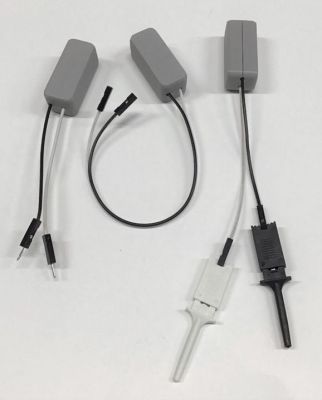
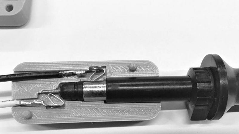
The two-part 3D printed assembly embeds a pair of wires with a Molex 0008500113 sprung terminal on one end, which can be terminated with your choice of pins, headers or just a pair of plain ‘ol wires. Once you’ve dropped your wiring of choice inside, simply glue the halves with a little cyanoacrylate and you’re good to go. Designed around the Siglent 200MHz PP215 specifically, it is likely compatible with many other brands. Thingiverse only has STL files (sigh!) so it may be tricky to adapt it to your exact probe dimensions, but the idea is good at least.
There is no shortage of electronics probing solutions out there, and boy have we covered a few over the years, here’s a low-cost current probe, an Open Source 2 GHz scope probe, and if you want to get really hacky, look no further for inspiration than the 2019 Hackaday SuperCon SMD Challenge.
Thanks [daniel] for the tip!


In our lab we had to put anti theft devices on the scope probes because they 10:1 away.
https://www.youtube.com/watch?v=9Jz1TjCphXE
:-)
https://images.app.goo.gl/UKKDaANnsTZpuzZC7
If you zoom in you’ll see the padlock on the scope probes.
If you’re going to dispense with the hook probe and replace it with cheesy flying leads, why not just run a piece of RG-174 to the BNC connector directly? (Well, I can think of a couple of good reasons in certain circumstances, but I’ll wait for the flamers to point them out)
A x10 probe loads the circuit a lot less, and a direct connection to the scope would need to be terminated properly. There is a reason a probe is more than a cable ending in a pin.
That said, I have done that in the past, with a 50R resistor in series and 50R terminator at the scope.
The flying leads aren’t exactly great for high speed signals either, especially if there are noise sources such as switchmode converters nearby, but there are plenty of cases where this is sufficient and convenient.
“…a direct connection to the scope would need to be terminated properly.”
Seriously? Who else but an electronics engineer would be doing this?
Technicians, hobbiests.
The probe is not just a piece of wire with pointy ends.
There is a resistor + cap trimmer (for frequency compensation) inside the probe. For a 10:1 probe, it is usually a 9M resistor and termination (programmable to 1M) inside the scope.
The resistor reduces the load on the signal being probe. At high frequency it doesn’t take too much capacitance (cable and scope input capacitance) to have become a low impedance.
Years ago I bought a used Heathkit o-scope. (One of those with the weak HV Supply).
As it didn’t come with a probe, I put a BNC and alligator clip on a length of coax to view waveforms.
Come to think of it, I’m not sure if I used a 50 ohm BNC or coax…
…not that it would have made much of a difference with that ‘scopes capabilities.
B^)
A few years later gave the scope to grade school science department.
For anyone interested in the real behaviour of scope probes, I’d highly recommend the article: “The Secret World of Oscilloscope Probes” by Doug Ford. It’s very clearly written and illustrated. A PDF copy is quite easy to find online, and you don’t need advanced knowledge or mathematical ability to understand it.
Thank you very much. My lunch break reading is set.
Maybe someone can turn one of those blood glucose meters into a scope probe.
I made something like this years ago with a prefboard and some discarded component leads. I then took some coax and made adapters such as alligator clips, Dupont connectors and IC hooks. I was planning to use a aluminum box but lost interest.
Where can I upvote this idea?
You just did.
Being STLs on Thingiverse isn’t that bad. These things have very simple geometry. You could model some in openscad in 5 minutes or so. That could be a good hobby: Taking non-scad files and making scad files out of them. =)
I’m sure there are scads of files out there waiting to be… uh… scadded?
B^)
CT3679 does exactly the same for ~$20, not sure if this can be considered eye-watering or even pricey. Printing is easy, flipping through a pair of catalogs is hard.