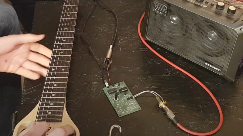
Earlier this year, we featured an unusual radio receiver that took the very traditional superhetrodyne design and implemented it in an unexpected fashion without any inductors, using instead a combination of 74HC logic chips and op-amps. Its designer [acidbourbon] remarks that the circuit bears a striking resemblance to a ring modulator,so has taken it down that path by producing a 74HC based ring modulator guitar pedal.
In both circuits, a 74HC4046 phase-locked loop chip serves as an oscillator, driving a 74HC4051 analogue switch chip that performs the mixer task. The extra-op-amp filter and demodulator circuitry from the radio is omitted, and the oscillator frequency moved down to the audio range. The result can be heard in the video, and we probably agree with him that it’s not quite the same as a classic ring modulator. This lies in the type of mixer, the diodes used in a traditional circuit have a forward voltage to overcome before they start or end conducting, while the CMOS switch chip does so immediately on command.
The 4000 series CMOS and their descendants are a fascinating family with many unexpected properties that our colleague Elliot Williams has gone into detail with for his Logic Noise series. Meanwhile take a look at our coverage of the original radio.


Brother man… this was beautiful. *stands*
*claps and doesn’t stop*
Thanks brother man!
This would work great in a rocker (wah type) foot pedal so you could do all those wild sounds using your foot instead of hand-on-dial.
I like your way of thinking.
Dino’s 555/386 based tremolo first and then this thing for sure ;)
More like this! Logic Noise was great. I built the Klangorium and incorporated it into my micro modular synth set up (Moog Werkstatt, Volca Modular, Sound Machines Nanosynth and a bunch of Bastl stuff).
Interesting idea:
Old TVs are a good source of delay lines of the acoustic (ultrasonic) variety for the luminance.
Could one of these be leveraged into a pedal if suitably foam encased and protected?
I have a stash of dead TV boards here, and they were somewhat common on CRT sets.
Also possible: wind your own delay line using copper tape, a former and old wire from a now broken
kinetic torch, heatshrink then wind more copper tape on top and connect the two ends.
It would take a while but I have done this once before for a TEA2000 based encoder.
MC1377 is in my box o’bits here and also the advantage is its fully analogue.
Essentially you encode the raw audio stream onto an RF carrier, feed into the delay line and then
mix it back out to recover the original signal.
I did also see a variant using a very old camera CCD, where you used the undocumented test input
to inject a signal then got it back out at the other end through the existing video out pins.
At a pinch a filtered VCSEL on the top left pixel will also work.
Colour does not matter as there was typically a common input so worst case the signal was chopped
Strange, my other comment got deleted which was a shame as it contained much useful data.
Incidentally old TVs have a nice acoustic delay line which can often be scavenged intact and recycled.
These days most of these functions are integrated.
Athother option is to use my method, which is an old small (2.5″) or smaller HDD, with its platter coated with ZnS and
then a row of blue or aqua 0603 LEDs to charge the phosphor and an analogue switch IC to shunt the data between LED/sensor pairs.
Its horribly kludgy but works.
If anyone does for any reason do this, please contact me so I can advise how to set up the switches as
there is a specific configuration that ensures maximum delay with minimum noise.
Most HDD motors will work just fine at low RPM, and for this application are remarkably robust.
I think that’s a bad sound, Hendrix could have use that in his day, he’s probably looking at it right now and saying, WHAT I CAN DO WITH THAT MAN. !!!!!!