A couple of weeks ago, [Doug Brown] bought a Ryzen motherboard, advertised as “non-working” and discounted accordingly. He noticed that the seller didn’t test it with any CPUs old enough to be supported by the board’s stock BIOS revision, and decided to take a gamble with upgrading it.
Not having a supported CPU in hand either, he decided to go the “external programmer” route, which succeeded and gave this board a new life. This is not why we’re writing this up, however. The reason this article caught our eye is because [Doug]’s research leaves no stone unturned, and it’s all there to learn from. Whether through careful observation or thorough research, this article covers all the important points and more, serving as an example to follow for anyone looking to program their BIOS.
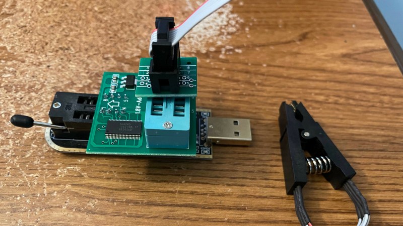
For instance, [Doug] correctly points out a design issue with these common programmers resulting in 5 V getting onto the 3.3 V data lines, and fixes it by rewiring the board. Going through all the letters in the ICs part number, something that many of us would dismiss, [Doug] notices that the flash chip is 1.8 V-only and procures a 1.8 V adapter to avoid the possibility of frying his motherboard. After finding out that the 1.8 V adapters don’t work for some people, he reverse-engineers the adapter’s schematics and confirms that it, indeed, ought to work with the specific parts on adapter he received.
Noting another letter in the part number implying the flash chip might be configured for quad-SPI operation, he adds series resistors to make sure there’s no chance of the programmer damaging the BIOS chip with its hardwired pinout. This is just an example of the insights in [Doug]’s article, there’s way more that we can’t mention for brevity, and we encourage you to check it out for yourself.
With this level of care put into the process, it’s no surprise that the modification was successful. The kind of inquisitiveness shared here is worth aspiring to, and writeups like this often surpass general-purpose tutorials in their insights and usefulness. What’s your “successfully making use of something sold as non-working” story?
If you’re looking for other insightful BIOS stories, we’ve covered someone reverse-engineering their BIOS to remove miniPCIe card whitelisting. We’ve typically covered BIOS modification stories in laptops, since there’s more incentives to modify these, but a lot of laptop BIOS articles will apply to desktop motherboards too, such as this supervisor password removal story or this LibreBoot installation journey by our own [Tom Nardi].
Thank you [Sidney] for sharing this with us!


>It consists of an AMS1117 linear regulator to create a 1.8V power rail from 3.3V, a few capacitors (I’m curious if an electrolytic cap should be on there too)
Unfortunately they have ceramic cap for the AMS1117 output which is known to cause instability (i.e. oscillation). AMS1117 is old parts so they weren’t designed with ultra low ESR bulk ceramic caps in mind. A electrolytic or adding a small value series resistor to the ceramic is what I would use.
IMHO, it seems to be a risky take on ebay item. The risk is higher than the cost for the board as it could fried up **other parts** you have. I recently bought a new Asrock Phantom Gaming 4 that comes with a $50 rebate (approved and cheque is in the mail). It came out to be around $50. The BIOS was up to date, so no messing around.
>With the original dump intact, it may be possible to locate where the special configuration info is located and reinsert it back into the chip
That’s the most important part about trying to fix firmware that got bad. That is no way to restore those custom records for your device from the vendor ROM firmware download.
I had some similar fun trying to test out Coreboot a few years back. Ended up fixing a bricked motherboard by swapping the BIOS chip onto another motherboard, while it was booted, to write the good firmware back. After a few of these hair-raising hot-swaps, because of course it didn’t work the first time, I managed to get both machines booting again. Neither with Coreboot, though. Turns out that while the project explicitly advertised support for my motherboard, it had no support for any of the processors the board supported. Go figure.
Oh, that is curious! Do you happen to remember the model of your mainboard?
I wonder if that list is supporting the motherboard chipset only – sometimes a chipset will get used across processor generations/sockets etc, so the motherboard is perfectly supported by coreboot, but you can’t use the CPU’s it will take because its got the ‘wrong’ socket on, at least till coreboot is updated with support…
I’ve been meaning to try a coreboot for ages and never got round to it, ended up down the rabbit hole of arm device tree type stuff needed for booting most recently, and haven’t actually got round to do anything with that research yet…
So, what you’re saying is if you identify parts and read their data sheet you can make stuff work? Who knew?
Seriously though, if more people would just do this even a fraction of the time we’d have fewer stupid questions on various forums.
Yeah, though half the time it’s because people never learned to read part numbers or data sheets.
Probably wouldn’t hurt with a “component identifying and data sheet sourcing & reading for dummies” guide, to throw in their direction in lieu of a “just fucking #SEARCH ENGINE# it” link.
Though I’d give some leeway for datasheets from small, specialized, or bootleg’ish manufacturers since it’s often a pain to decipher the info they give you, IF you can find them in English and with no silly NDA in the way.
But there are parts for which there’s no EXACT match of documents available online. Part of the part number is right but the data sheets available have nothing in them about some of the other letters/numbers in other positions in the part number, so you know it’s a specific capacity of flash chip by X company, but it may have some special features you can’t find info on.
I’d guess there are lots of people who do things because they read it on the internet. All isfine, mostly, if the instructions are detailed, and followed exactly. But if they fall off the path, they are lost. They don’t have a foundation, so don’t know how to read datasheets, or even know about them.
We have interweb search engine, datasheet, app. note etc on the web and yet people don’t bother reading them simply **BECAUSE** they are lazy. They don’t want to read few tens of pages of technical documents and would rather outsource the critical thinking to some random youtube channels. Back in the days, I had paid to receive datasheet from mail order places for parts I buy.
I ROTFL at “How do I become a hacker?” question popping up in HaD.io everytime. Bud if you don’t bother to do your own research and relies on been spoon-fed, then the hacker’s life is not for you.
Quick and dirty: hex-edited a compiled Linux kernel module (and associated files) to add a USB ID for a device that was supported but not listed within the module (USB-serial chip integrated into device).
Same device different day, this time for Windows support: dumped firmware from chip, hex-edited it to change from the device-maker’s USB ID to the standard chip-maker’s ID, and flashed the updated firmware back to the device.
Can you fix hacked USB drives and SD cards to show their true capacity? For example some “1TB” that’s really only 16GB? Scammers are able to hack them to show a bogus too large capacity, so it should be possible to undo what they do.
FYI, you can assign an unsupported vid/pid to a Linux usb driver at runtime, see the “new_id” sysfs entry here:
https://www.kernel.org/doc/Documentation/ABI/testing/sysfs-bus-usb
There is also a good video about the 3.3V fix here:
https://www.youtube.com/watch?v=-ln3VIZKKaE
I hit the same problem with those dongles trying to use some of its pins as a /sys/class/gpio entries, but I needed to connect them to 3.3v devices.
Other ch341a boards have a jumper, and they are not much more expensive, just a little bit harder to source:
http://zoobab.com/ch341-usb-spi-i2c-uart-isp-dongle
Someone should find the manufacturer of those ch341a flashers, and launch a public petition to add a voltage jumper to select 3.3v or 5V!
A video about the 3.3V fix:
https://www.youtube.com/watch?v=-ln3VIZKKaE
I have listed some other ch341a boards that have a proper 3.3V-5V jumper:
http://www.zoobab.com/ch341-usb-spi-i2c-uart-isp-dongle
I wonder how much he spent on this learning exercise? The lowest price CPU that should be compatible with this board before updating the BIOS is a Ryzen 3 3100, lowest price I can find is $109.19 from govgroup dot com
When I had a similar problem, I bought the cheapest CPU I could that was compatible, used it to flash the BIOS, then sent the CPU back to a certain retailer (named after a big river) and got a refund.
Kudos on this “refurbishing” exercise for sure. Nice work and a rewarding outcome. Most of my own recovery purchases involve Drake radio equipment from hamfests and listings on QRZ and ePay. And while most of those can be brought back to life with some effort, other project pieces are better left dead.
But on a few rare occasions, “the fix” for a “not working – for parts only” device takes nothing more than a little bit of observation and very minimal action. A few years ago I bought a “DOA” under-counter ice maker during a going-out-of-business sale by a local appliance vendor, for $25. It was brand new but returned to the vendor as DOA. No parts were missing and even the owners manual was still taped to the inside ice bucket. Once I had it home, I hooked up a water supply and plugged in the power cord. Yup…dead as expected…prior to turning on the power switch concealed behind the removable front panel. As soon as I flipped that switch on, she came to life and hasn’t stopped spitting out a full load of ice every day since. There is no substitute for observation in diagnosing a problem.
I had an Asrock B85 mini-ITX motherboard that had went out on me a few years ago; I remember trying to turn my pc off one day and it wouldn’t through normal means, so I had to hold down the power button to do it, and next time around it would power on for a few seconds and turn off, so I initially figured that the motherboard had just died, and eventually replaced it with an H97 mini-itx board. I still have the board since I had tried to determine what the problem was; I even asked around on forums too, but everything seemed to be leaning towards the board had just died, so I just put it back in the box and left it alone.
After reading this article though, maybe the board isn’t as dead as I think, but maybe a part on the board just might needing repaired or something, so I’ll consider giving it another look when I can find a cpu to use it with, although I’m nowhere near as adept as Doug is with dismantling boards, but I still feel inspired to see if there’s a chance that it can be fixed and repurposed. Thanks a lot for posting this Hackaday!