The Arduino is a powerful platform for interfacing with the real world, but it isn’t without limits. One of those hard limits, even for the Arduino MEGA, is a finite number of pins that the microcontroller can use to interface with the real world. If you’re looking to extend the platform’s reach in one of your own projects, though, there are a couple of options available. This project from [Bill] shows us one of those options by using the ATtiny85 to offload some of an Arduino’s tasks using I2C.
I2C has been around since the early 80s as a way for microcontrollers to communicate with each other using a minimum of hardware. All that is needed is to connect the I2C pins of the microcontrollers and provide each with power. This project uses an Arduino as the controller and an arbitrary number of smaller ATtiny85 microcontrollers as targets. Communicating with the smaller device allows the Arduino to focus on more processor-intensive tasks while giving the simpler tasks to the ATtiny. It also greatly simplifies wiring for projects that may be distributed across a distance. [Bill] also standardizes the build with a custom development board for the ATtiny that can also double as a shield for the Arduino, allowing him to easily expand and modify his projects without too much extra soldering.
Using I2C might not be the most novel of innovations, but making it easy to use is certainly a valuable tool to add to the toolbox when limited on GPIO or by other physical constraints. To that end, [Bill] also includes code for an example project that simplifies the setup of one of these devices on the software end as well. If you’re looking for some examples for what to do with I2C, take a look at this thermometer that communicates with I2C or this project which uses multiple sensors daisy-chained together.


I would suggest something like an NXP PCA9698DGG, 512 if you really need more GPIO from an Arduino, but each to their own….
I’ve seen these on Ali but would they handle lots of blue LEDs with high currents?
I still want to build a large dashboard one day that monitors various services that run on my servers.
I’ve tried MOSFETs and the alike, but I had nasty ghosting. Sadly I can code better than design circuits .w.
Please throw me a bone where to read. Someone must have achieved this. The circuits I’ve rebuild didn’t work due to ghosting.
Did you have a pulldown resistor?
Yes, tried a few values for pulldown. But I had no resistor to protect the gate. Some circuits show one, others don’t. Could I have damaged the gate?
Addendum: 2N7000 and BS170
You shouldn’t have damaged it, check the datasheet and look at the reference design but it should work like many other examples for n channel MOSFETs. They do work with a pulldown resistor if your signal only drives high. If your signal signal or gpio can drive it to ground too then you should need a pulldown resistor. Make a basic circuit on a breadboard with an led and resistor, a MOSFET and just use a wire connected to the gate to manually connect it to 5 V and ground. For that test don’t use any pulldown resistor. Then after that try toggling it with a gpio pin on a microcontroller, they can source or sink current and as long as the charge on the gate can go to ground when it’s supposed to be off it should work. If you are using it with something like a simple pushbutton though then that’s when you need a pulldown resistor, because the button will only connect it to vcc when pressed but when released it will just break the connection it won’t ground the gate. I don’t think MOSFETs really need a gate protection resistor, they should work fine without. Just make sure you don’t draw too much current through the MOSFET that will make it heat up and possibly burn out.
@Conor
That’s the thing: I had them on a breadboard and the same circuit would result in different glow intensities of the LEDs. I wondered if a gate was stuck, so I changed the pulldown resistor value, but the only way I could influence it was swapping the MOSFETs themselves. Half of them would ghost stronger, some would ghost very lightly. Only on a manual full pulldown the LED would extinguish fully. So yes they would work, but not in the circuit they were designed for unless I want them to glitch. The parts were handed to me brand new from an electronics store in town in a paper bag. Luckily they came so cheap i never bothered returning them.
A decent way to do this is: fet source is ground, drain is attached to the LED. 10 ohm resistor between microcontroller and fet gate, and 10K resistor from fet gate to ground.
There are also specialized matrix manager chips that are designed specifically to provide constant current and individually addressable control to significant numbers of LED’s, although that’s probably overkill. But it sure helps the scalability problem.
BTW you’re unlikely to damage the fet gate if you don’t have a current-limiting resistor between uC and FET. You are more likely to damage the uC because the fet’s gate can draw a significant current, exceeding the uC’s ability to safely source.
What is your supply voltage? What is the led current and the value of the led resistor? With 5V you should have plenty of headroom for both the gate drive and the led, with 3.3V you might be operating on the edge of gate turn-on for the 2N7000 and/or a blue led’s turn on.
A series gate resistor (~100 ohm) is used sometimes to suppress HF oscillations in some fet’s; a resistor in parallel with the gate is sometimes used as a pulldown. Neither is strictly necessary in all circuits. Lack of either will not result in gate damage.
why not use neopixels
If you want to drive lots of LEDs use a MAX7219 instead, it’s literally designed to allow you to drive 64 LEDs from a single SPI bus (idk if there’s an I2C version)
But, fwiw, the NXP PCA….. I mentioned can do a lot of LEDs, too.
Have you tried using neopixels instead of LED,s. They can be programmed to any colour and only use 1 pin total. Powered by a 5vdv supply.
This is definitely not new, it is quite a basic thing to do with i2c, I used 6 Arduino nanos driving 3 steppers and potentiometers each communicating through i2c with an Intel Galileo for a high school project. This is just using i2c for what it’s designed for. Could have at least picked a better microcontroller. Using an ATTiny because you ran out of pins when it only has 8 pins, so two for power, two for i2c you are only left with 4 pins, not very useful and the argument you can place the ATTiny at a distance doesn’t really work because i2c doesn’t have much range, sure it will extend the distance a bit but not by much.
I beg to differ. As a jokey experiment a friend and I controlled a MCP23017 IO expander with a 12m bus cable of screened 4 core security cable. I can’t remember if we actually grounded the shield though. It seemed to be surprisingly solid for the 20 minutes or so we were mucking about. Point being, for something designed as an interchip bus, I2C is actually pretty rugged over a resonable distance using a very much less than ideal bus configuration.
Haha. No. Dont do this. The Ultimaker 3 I2C cable of 1m has caused a lot of headace. I2C is designed for perfect signal quality, else you get artbitration loss and nobody to release the bus.
The problem is that it will work until it doesn’t. If you’d, for example, run a power line next to the two signal lines in that cable to run something relatively high-current off of a relay controlled by the I2C signal (similar to this article, just something where a relay would have been more useful, like a DC motor), you could easily introduce common-mode noise and utterly destroy your signal integrity. Even with your shielding, high-current AC items near the endpoint could ruin one’s day while doing this.
And then we get to the propensity that a number of I2C devices have to deadlock the bus if they receive a slightly incorrect packet, for errors ranging from a missing bit to something as benign as undefined address.
Working for you once is not a reason to recommend extending a PCB bus over long cables. It’s easy enough to get any of a variety of protocols working over RS485, especially if one is implementing it in an MCU anyways, as in the video.
>because i2c doesn’t have much range
It all depends on frequency and you can get active pullups to make things better. I am running a very slow I2C with iirc 5kHz over 20m unshielded cable without any problems. Yes, it is not made for such things but for personal use its just fine and cheaper and simpler than other busses that need more circuitry. However implementing an I2C-slave in software with really limited ressources was somewhat of a pain…
Ah hmm, has anyone used a sizable io wide port CPU to do a single clock to all devices buffered & synced with psuedo parallel data from all those multiple devices at same time, then to map these into arrays in the cpu with some indexing, it’s just a different way to do lots & lots of multiple serial input most easily though with output a minor masked variant of that by device type ?
Thanks for post, nice to see, cheers
Nice project!
I made 2 circuits using this idea, but using an ATtiny841:
https://wiki.logre.eu/index.php/Joystick_Node
https://wiki.logre.eu/index.php/Servo_Node
The ATtiny841 has a hardware I²C slave port, which makes the dev. very easy, and free a lot of bytes for the main code.
I speak from experience that the USI (or whatever it is called) “partial hardware” thing in the Tiny85 leads to a highly unreliable slave device. On a regular basis the slave would actively pull up the bus (I2C devices are NOT supposed to do this!), leading to it playing “bus fighter” against the master.
Thanks for this information, i have to check if there is an errata from Atmel for this.
In the ideal world one uses an ATMEGA328 as the I2C slave, it is effectively a second arduino (once you an an osc crystal) in DIP28 packaging and can obey all sorts of coplex commands you chosoe to define, and has loads of pins to do so on. An ATTiny doesn’t usually have enough GPIOs to be much use as a GPIO expansion slave. Shame the chip crisis is making 328s so hard to get right now, lead times of >1 year for SMD versions.
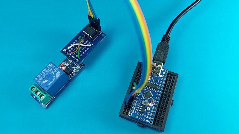
In the photo, we see an Arduino Nano connected to an ATTiny85, connected by 4 wires, 2 for power and 2 for IO. The use case looks to be switching on or off a mechanical relay. A mechanical relay needs 3 wires, 2 for power and 1 for any old analog HIGH/LOW signal. So this project will double my GPIO usage, and provide a weaker signal? Sign me up.
But what if you need 10 relais at different places? Yes, we can always discuss if I2C over long wires is a good thing, but don’t forget that it is an adressable bus.
Interesting. I have but attiny85 slaves in the past and though i love that chip, it has become too expensive for what it offers. Never seen it for 50 cts, even before the chip shortage.
Now what would be interesting is the i2c implementation on an attiny 13A.
I2C on an t13A is certainly possible, BTDT. A bit fiddly perhaps but possible.
What about a Padauk? One of the 7 cent or so ones. Some of them have lots of pins.