When it comes to fields that are considered the most complex of human endeavours, the most typically cited are those of rocket science and brain surgery. Indeed, to become a surgeon is to qualify in a complex, ever-changing, and high-performance field, with a pay scale and respect to match.
The tools of surgery have changed over time, with robotic assistants becoming commonplace in recent decades. Now the latest robots are starting to outperform human surgeons in some ways. Let’s look at how that’s been achieved, and what it means for the future of medicine. Continue reading “Robotic Surgeons Are Showing Hints Of One Day Outperforming Humans”→
A few weeks ago, some tantalizing social media posts emerged from a Def Con talk, in which [Sick Codes] broke into the screen control unit for a John Deere tractor live on stage, and proceeded to play a special Deere-themed DOOM level upon it. At the time there was nothing more to go on, but we’re pleased to find out that the whole talk has been put online.
The talk starts with an introduction to the topic, to the basics of the control units within the machine and to the various different ages of Deere screen unit. We find that the earlier machines, which are still at work on farms worldwide, rely on outdated Windows CE versions, though the very latest screens run a Linux variant.
It’s one of these last screens to which he turns his attention, and we’re treated to an in-depth look at some of its secrets. After a lot of dead ends and learning exercises the final result is distilled into a pogo pin adapter for the hardware part, and a simple enough cron job to bypass one of Deere’s defenses by keeping the filesystem writable so a file can be updated. There’s a bit more detail about the special DOOM level too, as a special bonus.
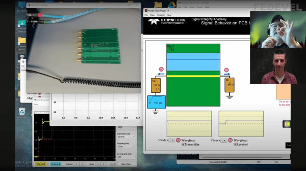
PCB design starts off being a relatively easy affair — you create a rectangular outline, assign some component footprints, run some traces, and dump out some Gerber files to send to the fab. Then as you get more experienced and begin trying harder circuits, dipping into switching power supplies, high speed digital and low noise analog, things get progressively more difficult; and we haven’t even talked about RF or microwave design yet, where things can get just plain weird from the uninitiated viewpoint. [Robert Feranec] is no stranger to such matters, and he’s teamed up with one of leading experts (and one of this scribe’s personal electronics heroes) in signal integrity matters, [Prof. Eric Bogatin] for a deep dive into the how and why of controlled impedance design.
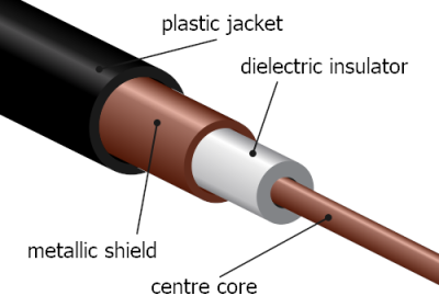
RG58 cable construction. These usually are found in 50 Ω and less commonly these days 75Ω variants
One interesting part of the discussion is why is 50 Ω so prevalent? The answer is firstly historical. Back in the 1930s, coaxial cables needed for radio applications, were designed to minimize transmission loss, using reasonable dimensions and polyethylene insulation, the impedance came out at 50 Ω. Secondarily, when designing PCB traces for a reasonable cost fab, there is a trade-off between power consumption and noise immunity.
As a rule of thumb, lowering the impedance increases noise immunity at the cost of more power consumption, and higher impedance goes the other way. You need to balance this with the resulting trace widths, separation and overall routing density you can tolerate.
Another fun story was when Intel were designing a high speed bus for graphical interfaces, and created a simulation of a typical bus structure and parameterized the physical constants, such as the trace line widths, dielectric thickness, via sizes and so on, that were viable with low-cost PCB fab houses. Then, using a Monte Carlo simulation to run 400,000 simulations, they located the sweet spot. Since the via design compatible with the cheap fab design rules resulted often in a via characteristic impedance that came out quite low, it was recommended to reduce the trace impedance from 100 Ω to 85 Ω differential, rather than try tweak the via geometry to bring it up to match the trace. Fun stuff!
We admit, the video is from the start of the year and very long, but for such important basic concepts in high speed digital design, we think it’s well worth your time. We certainly picked up a couple of useful titbits!
Now we’ve got the PCB construction nailed, why circle back and go check those cables?