All About USB-C: Resistors And Emarkers

If you’ve been following along our USB-C saga, you know that the CC wire in the USB-C cables is used for communications and polarity detection. However, what’s not as widely known is that there are two protocols used in USB-C for communications – an analog one and a digital one. Today, let’s look at the analog signalling used in USB-C – in part, learn more about the fabled 5.1 kΩ resistors and how they work. We’ll also learn about emarkers and the mysterious entity that is VCONN!

USB-C power supply expects to sense a certain value pulldown on the CC line before it provides 5 V on VBUS, and any higher voltages have to be negotiated digitally. The PSU, be it your laptop’s port or a charger, can detect the pulldown (known as Rd) because it keeps a pullup (known as Rp) on the CC line – it then checks if a voltage divider has formed on CC, and whether the resulting voltage is within acceptable range.

If you plug a device that doesn’t make a pulldown accessible through the CC wire in the cable, your device will never get power from a USB-C port, and would only work with a USB-A to USB-C cable. Even the smarter devices that can talk the digital part of USB-C are expected to have pulldowns, it’s just that those pulldowns are internal to the USB-C communication IC used. A USB-C port that wants to receive power needs to have a pulldown.

This part is well-known by now, but we’ve seen lack-of-resistor failures in cheap devices aplenty, and the colloquial advice is “add 5.1 kΩ resistors”. You might be afraid to think it’s so simple, but you’d be surprised. Continue reading “All About USB-C: Resistors And Emarkers”

Squeezing A Minimalist 6502 Retrocomputer Onto A Single Breadboard

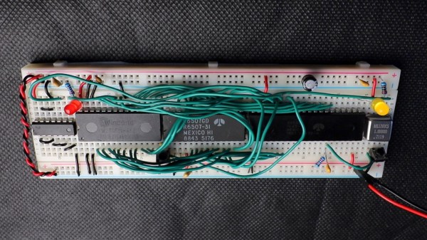
Over the years, and especially lately, we’ve seen tons of single-board retrocomputer builds. That’s fine with us — the more, the merrier. But they all start to run together a bit, with little to distinguish between them. Not so this about-as-compact-as-possible 6502 computer that fits on a single breadboard.

Now, when you do the math, it seems like there’s no way that [Anders Nielsen] would have been able to fit even a minimal chipset onto a standard solderless breadboard. The 40-pin 6502 alone takes up nearly two-thirds of the connections available; add in equally large but necessary chips like the 6522 interface adapter, ROM and RAM chips, and some support ICs, and one breadboard isn’t going to cut it. Luckily, some frugal engineers at MOS back in the 70s came up with the 6507, a variant on the 6502 in a 28-pin DIP. The other key to this build is the 6532 RAM-I/O-timer chip or RIOT, which puts a tiny amount of RAM and some IO lines on a single 40-pin DIP. Along with a 28-pin ROM, a 14-pin hex inverter, and a little crystal oscillator, the entire chipset just barely fits on a single breadboard.

But what can this minimalist 6502 actually do? As you can see in the video below, anything a 555 timer can do, and maybe a little bit more. That’s not a dig, of course — [Anders] actually calls out his initial blinkenlight application as a little more than a glorified 555, and actually comes up with a marginally more complex application just to prove the point. The interesting part here is dealing with the constraints imposed by the limited resources available on this machine.

We’re looking forward to whatever comes next for this clever build. It’s hard to see how some of the plans [Anders] has for it will still fit on a single breadboard, though — these things tend to spread out as they go.

Continue reading “Squeezing A Minimalist 6502 Retrocomputer Onto A Single Breadboard”

Bypass Defective STDP9320 Video Controller On Wacom Cintiq Companion 2

Some products seem to have a part of two that’s pretty much guaranteed to end up dying on you. In the case of the 2015-vintage Wacom Cintiq Companion 2, this turns out to be the so-called Athena chip, which switches the display input between the HDMI port and internal display controller. This allows for use in both standalone mode (tablet), as well as companion mode, where it acts as a drawing tablet for a connected PC. When confronted with such a faulty device, [neutrino] found and applied a simple fix: bypassing the Athena chip altogether.

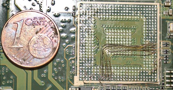
This fix is recommended by the Repair Preservation Group’s wiki page on the topic, noting that this will permanently disable its use as an external display without additional repairs to recreate the functionality of the removed chip. This STDP9320 (PDF) part by ST Microelectronics is described as a ‘Premium high resolution multimedia monitor controller with 3D video’ and contains a wide range of video scalers, a HDMI receiver, DisplayPort (including embedded DP) support. With this fix, the Cintiq Companion 2’s Intel CPU’s graphics core is directly connected to the display’s eDP input, along with a range of voltages and enable pins.

What the exact reason is for the STDP9320 dying after a few years with what appears to be some kind of internal power failure or short, but this bypass fix at least restores standalone functionality. Sourcing a replacement for this obsolete IC seems possible, but a big gamble. Sadly, it would seem that this Wacom device will no longer be a companion for much longer.