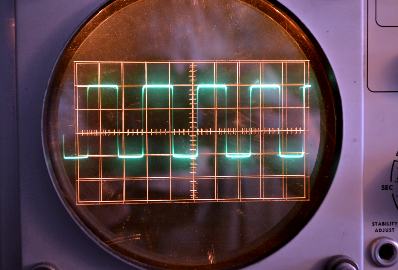
Oscilloscopes are great for measuring the time and voltage information of a signal. Some old scopes don’t have much in the way of markings on the CRT, although eventually, we started seeing scales that allowed you to count squares easily. Early scopes had marks on the glass or plastic over the CRT, but as [Vintage TEK Museum] points out, this meant for best accuracy, you had to look directly at the CRT. If you were at an angle horizontally or vertically, the position of the trace would appear to move concerning the lines on the screen. You can see the effect in the video below.
The simple solution was to mark directly into the phosphor, which minimized the effect. Before that was possible, [Bob Anderson] invented a clever solution, although Tektronix didn’t produce any scopes using it for some reason. The idea was the virtual oscilloscope graticule, and it was quite clever.
The idea was to put the graticule on a semi-reflective mirror. Looking through the assembly, you would actually see the trace and the reflection of the graticule in the mirror. The resulting image is perfectly aligned if the assembly is constructed properly. You can, at some angles, see both the front and reflected graticules.
According to the video, management was not impressed because someone other than [Anderson] showed a poor-quality prototype to them. By 1962, the graticule in the phosphor took over, and there was no need for [Anderson’s] clever invention.
These days, a graticule is just bits on the screen. Even if you roll your own.


Interesting idea, useful if you want to make a fixed mark or division on top of an OLED screen.
The D1=D2 is not perfect if you’re working with different materials, as you have angles of refraction to combat.
Sharpie marker and a ruler.
Another trick for single channel Scopes and you needed to compare a trace you would use a grease pencil and trace over the first signal then connect the probe to the next signal then you could compare them.
With several years’ experience using the Tek 545A, I found that moving my head to get the green worm to line up with a graticule line was usually easier than doing fine adjustments with the position controls. But still, I was happy when I upgraded to a ‘scope with an etched graticule.
The cool thing about optically aligned graticules, though, is that you can switch graticules for special measurements, without producing parallax errors.
A note about the video, though: the “example” of parallax on a ‘scope with a separate graticule is clearly fake. You can see that the camera angle has not changed, and the offset is more than you would see on a real ‘scope unless you were off axis by a mile. I can understand he probably didn’t have an old ‘scope on hand to prove this with, so just used two pictures that showed similar waveforms with an offset. Pro tip: leave the fake videos to AI, who know what they are doing. Sort of.
Not for digital scope out put .