We covered [Anders Nielsen]’s 65duino project a short while ago, and now he’s back with an update video showing some more details of bit-banging I2C using plain old 6502 assembly language.
Obviously, with such a simple system, there is no dedicated I2C interface hardware, so the programmer must take care of all the details of the I2C protocol in software, bit-banging it out to the peripheral and reading back the response one bit at a time.
The first detail to concern us will be the I2C addresses of the devices being connected to the bus and how low-level bit manipulation is used to turn the 7-bit I2C address into the byte being bit-banged. As [Anders] shows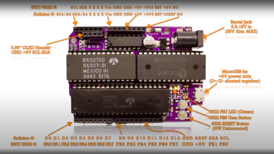 , setting a bit is simply a logical-OR operation, and resetting a bit is a simple logical-AND operation using the inversion (or one’s complement) bit to reset to form a bitmask. As many will already know, this process is necessary to code for a read or a write I2C operation. A further detail is that I2C uses an open-collector connection scheme, which means that no device on the bus may drive the bus to logical high; instead, they must release the drive by going to the high impedance state, and an external pull-up resistor will pull the bus high. The 6532 RIOT chip (used for I/O on the 65unio) does not have tristate control but instead uses a data direction register (DDR) to allow a pin to be an input. This will do the job just fine, albeit with slightly odd-looking code, until you know what’s going on.
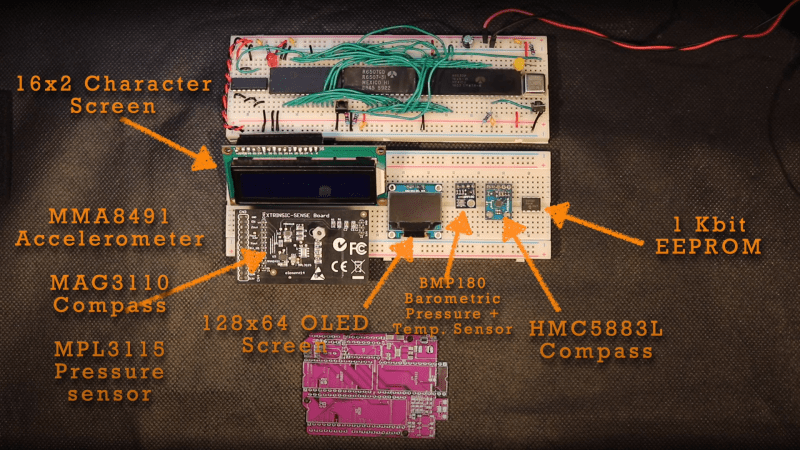
From there, it’s a straightforward matter to write subroutines that generate the I2C start, stop, and NACK conditions that are required to write to the SSD1306-based OLED to get it to do something we can observe. From these basic roots, through higher-level subroutines, a complete OLED library in assembly can be constructed. We shall sit tight and await where [Anders] goes next with this!
We see I2C-connected things all the time, like this neat ATtiny85-based I2C peripheral, and whilst we’re talking about the SSD1306 OLED display controller, here’s a hack that shows just how much you can push your luck with the I2C spec and get some crazy frame rates.


Takes me back to 6502 bit banging on the i2c interface to philips teletext tuner modules to provide real time news feeds via serial :-) Really cool at the time!
I would love to see a Hackaday article on this!
A lot of new engineers don’t get the subtle point that in doing this on a micro that there are conditions: the ‘open’ or hi level of the pin will be limited to the Vdd of the micro vs a ‘real’ open collector/drain IO. Most micro’s will have IO pin diode protection structures and will clamp the ‘open’ to near that voltage. For example, don’t expect the ‘open’ in the micro case to rise to 24vdc, even if the pullup is connected to 24v system. The pullups should be referenced to the micro’s vdd. BR, Lee
That is a very good point, thanks. It is something you can usually get away with missing though – for 3v3->5V interfacing.
As far as I know the 6532 (or 6522 for that matter) will actually pull up like a “real” open collector(no diodes – I might test that though) but in the case of 12/24V I would probably use an LM339 for it’s open collector outputs.
A simple diode can make an active high act like an open. I did this with an expensive I2C dongle when the manufacturer refused to modify their driver to support an I2C device with an 8 bit address. Their solution was to have me write my own code to bit bang off of the gpio pins on their adapter.