A good deal of the projects we cover here at Hackaday are not, in the strictest sense, practical endeavors. If we required that everything which graced our digital pages had a clear end result, the site would be in a rather sad state of affairs. Sometimes it’s enough just to do something for the challenge of it. But more often than not, you’ll learn something in the process which you can use down the line.
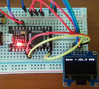 That’s precisely what pushed [Larry Bank] to see how well he could optimize the frame rate on the popular SSD1306 OLED display. After several iterations of his code, he was able to achieve a blistering 151.5 FPS, with apparently still some room for improvement if he’s feeling up to the challenge. But considering his first attempt was only running at 5.5 FPS, we’d say he’s already more than earned his hacker cred on this one.
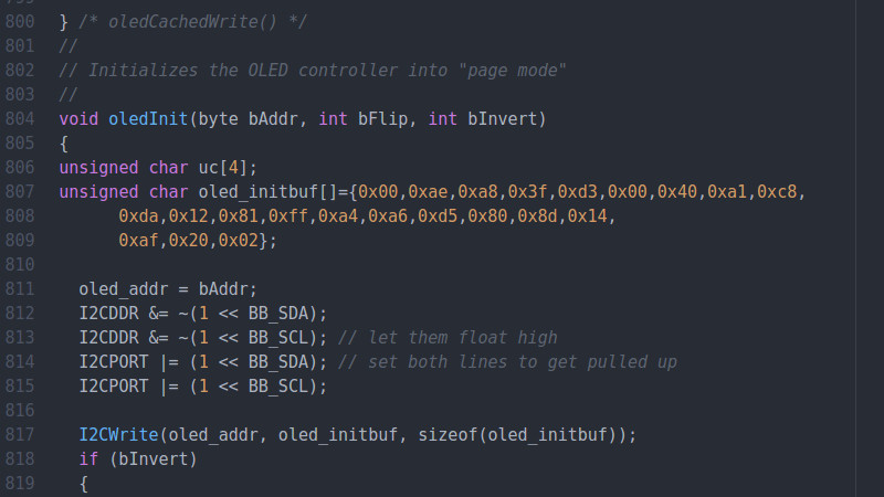
A few different tricks were used to achieve such incredible performance gains. To start with, while the official I2C specification says you’re supposed to wait for an acknowledgment back from the device when communicating with it, [Larry] realized the SSD1306 didn’t actually care. He could continuously blast commands at the display without bothering to wait for an acknowledgment. He admits there are problems with this method, but you can’t argue with the results.
To really wring all the performance out of the system he could, [Larry] donned his Assembly Cap and examined how the Arduino IDE compiler was interpreting his code. He identified a few areas where changing his C code would force the compiler to generate faster output. He notes that this wouldn’t normally be required when working with more advanced compilers, but that the Arduino toolchain needs its hand held occasionally.
This isn’t the first time we’ve seen somebody try and push more pixels through the very same OLED display, and it’s interesting to see the two very different approaches to the same goal.


Curious about the machine not caring if an acknowledgement was sent or not. I wonder what writer/programmer wrote that, and who dreamed it up? As a human, when I call a bank and get a machine, I know when the next click starts, ~”now enter…” that I can fire away. Why wait? But while you’re waiting, you might as well test things and see if you have to wait!!! It’s just like any boy-girl relationship…! ????
Way to go, LB!
Acknowledgement is important to keep from flooding the request queue. If a device only buffers say the last 3 commands (FIFO) and it takes 1 ms to process each command then you don’t wanna send more than 3 commands in a 3 ms window, otherwise you’ll drop commands.
Not to mention that i2c is often used in situations where the connection is unreliable or noisy.
Please read my blog post. The point of my code was not to comply with the I2C protocol, but to test the limits of the SSD1306. I pushed the boundaries to see what was possible and exploited it.
:)
The key thing to understand is that the controller chip also supports parallel IO, and the serial interfaces are just tacked onto that. So the video software isn’t even aware those protocols exist. And the chip adding the interface is designed to be robust and do just do whatever the application processor tells it, so errors are more likely to be reported on a pin than to change operation.
The boards often have all the parallel pins brought out on a flexible PCB that doubles as a connector between the glass part and the control board; the different control boards just add the external components for one of the supported interfaces. So making use of the parallel connection would be the more standard way to get the same speed; but that is a lot of pins. Doing it with serial means you can use a smaller package like an attiny85 or Digispark instead of atmega/Arduino.
However, the OLED itself refreshes only at about 60 Hz.
It’s been a few years, and it might have been a slightly different controller, so not sure my memory is correct..
But the timing parameters (which add up to the frame time) are reprogrammable, no..?
The picture quality/pixel stability might be affected, but there certainly are more than just a single one-fits-all set of parameters; so go ahead and play around.
However, some timings might be ‘bad’, i.e. increase wear or even damage pixels (over some time at least), so maybe not deviate too far from datasheet recommendations, and maybe not experiment in a production context :)
Markus, how do you get to the conclusion of 60 Hz refresh rate?
According to the datasheet : frm = Fosc / (D * K * M), where D is clk-divider (1..16), K is combined segment drive time per line, M is the line mux ratio.
Typical value for internal Fosc = 370kHz; D = 1, K = 54, M = 64 (for a 128×64 display). Default frame-rate should be 107 Hz. Really simple.
Assuming you want to maximize refresh rate, go tuning Fosc to max (cmd 0xD5) should send it to apprx. 540kHz (see “Figure 10-7 : Oscillator frequency setting” in section 10.1.16, detailing cmd D5). Although the spread is quite significant.
Typically it should result in a refreshrate greater than 150 Hz, however you might have to increase the pre-charge phases to compensate for the shorter DCLKs to avoid ghosting or reduced pixel quality.
OK, then I stand corrected. Haven’t seen those parameters back then when I used those displays. Thanks for the clarification.
https://www.youtube.com/watch?v=1msOr2tqvcs
That’s the SPI version of the display; this article is about abusing the I2C version of this display to get a higher frame rate.
And he still uses the Arduino IDE? How about not doing that and working actually barebone? Or working with an actually good microcontroller? Using Arduino for this would like trying to run foot race with a big backpack. Sure, you’ll be able to do it, but lose that backpack and you’ll probably improve your time.
Yes, he should do that and share the code. All we have to do is go out and buy an odd flavor of Renesas 32-bit microcontroller, build our own dev board because none exist on the market, collect the Windows-only hardware tools and software toolchain from various websites, get all of that working and tested, download his code from a Wayback Machine archived version of a defunct Google Code web page, resolve any incompatibilities with a newer toolchain, and integrate his code with our application.
I’ve lived this experience before, and having a (somewhat) common platform to share concepts is more valuable than you think. People getting paid a salary to spend months squeezing the last microwatt and penny from a design can go ahead and chase that dragon. The rest of us are pretty happy optimizing the parts we need to work better, and not polishing our Real Embedded Developer trophies.
There is GR-PEACH though. Not that it would be anyone’s first choice for anything, but it has rza1h.
What would be gained from working barebone? He’d have to write all the code to initialize clocks and everything for absolutely zero gain, none of it would actually speed up his code here, so he’d just be doing all that work for nothing when the Arduino-environment can do it for him for free. Also, again, what would switching to some other MCU give him? Sure, a faster MCU is faster, but the whole point here is in getting the code to be as fast as possible and switching to some other MCU wouldn’t change that.
Seems to me that you’re just whining because of the word “Arduino” here, instead of any actual properly-argumented reason.
Yeah, he’s using direct port access in a loop. All “Arduino” is is a collection of libraries that support cross-chip compatibility by mapping ports to pin numbers, along with a simple IDE. You can choose to use the libraries, or you can code to the metal if need be.
Yes, I know, and that’s why all the Arduino-haters just seem rather silly. All that foam coming from their mouths must be blinding them.
To be fair, I haven’t actually read the blog post, just this HaD article. What caught my eye, and what was the basis of my critisism was the following part of the article:
“To really wring all the performance out of the system he could, [Laurence] donned his Assembly Cap and examined how the Arduino IDE compiler was interpreting his code. He identified a few areas where changing his C code would force the compiler to generate faster output. He notes that this wouldn’t normally be required when working with more advanced compilers, but that the Arduino toolchain needs its hand held occasionally.”
To me, this implies that there were some limits that came from using an Arduino and the Arduino IDE (and not from the display itself or the protocol). I mean, you can only do so much using an 8-bit microcontroller @ 16MHz. If the goal is “I want to run this display at the highest possible framerate”, it would be reasonable to try and remove any limits, of which the code generated by the Ardunio IDE might be one, and the overall computing capabilites of the MCU (using Arduino implies using an Atmega328 at 16MHz).
Reading the blog post itself, it stated that he wanted to learn stuff about the Attiny85 and the I2C-protocol, in which case everything seems much more reasonable. I blame the article writer for leaving such details out.
In any case, I still don’t like Arduino very much, because I feel some kind of elitism and I always want to work extremely barebone. I wish I was better at re-using code and using other peoples code, but I’m just not, and I don’t know why.
That doesn’t bother me, I’m just exited that it implies I can easy do 30fps on an attiny and not have to implement the whole protocol and use up so much CPU time.
On a better chip like an MSP432 you can use DMA and you’d slow things down trying to implement half the protocol in the CPU, plus the regular serial drivers comes on the ROM. But it costs $6 in single quantities. The good news, you can get a full arduino-like board with a hardware JTAG debugger/emulator for $13.
But I’m paying about $1.50 for attiny85 on a board with a USB connector and voltage regulation. Using the SSD1306 in the wrong way ends up using most of the CPU time though. Like, the same chip can run black and white composite video (NTSC or PAL) but you only have a few cycles left to do anything else. This could mean being able to actually do something that would generate more frames per second! lol
Other improvements could be: remove loop and bit shifting. Also write SCL and SDA levels to the GPIO port at the same time without doing a read modify write. This would also affect the other 6 pins if the GPIO port, but probably improves speed.
The AVR has single instruction bit set/clear instruction for GPIO pins, so you are not getting a read-modify-write. I don’t think you will get any improvement the proposed method.
If you would need to set more then 2 GPIOs, then, yes, this would improve. But as it stand, you would write the “inner loop” as only 4 instructions I think.
If you want to go faster, you could unroll everything. Generate the proper set of instructions for each possible byte you want to send out, which would boil down to 18 clock flip instructions, and 8 data-bit set instructions. 26 instructions per byte value. 1 return instruction on top of that, so 27 instructions, times 256 different byte values, 6912 instructions. Less if you leave out the data-bit-set instructions that are not needed. Well within the flash storage for an Arduino. A lookup table can allow you to jump to the proper instructions quickly.
The SBI/CBI instructions that are used are 1 or 2 cycles depending on the chip. Worst case, you get 6 cycles per bit then, giving a 2.6Mhz clock rate. Or 5.3Mhz if the core is XMEGA. I forgot which spec to look at…
The SBI/CBI instructions, even though they appear to do their job in 1/2 clocks, are slower than just writing to the I/O port. I tested this and it made a significant speed improvement to hold the previous value of the I/O port in a local variable.
“To start with, while the official I2C specification says you’re supposed to wait for an acknowledgment back from the device when communicating with it, [Laurence] realized the SSD1306 didn’t actually care.”
Oh it cares, he has not done his testing right for it to show up. Writing a one line to show FPS is not a true test. The only true way is to fill the screen and clear it. That is the true FPS test.
Please read my blog post and look at the code I shared. I tested the performance by filling the display with different text and byte patterns. I tested all changes to make sure that the display code still worked before continuing.
actually, the way to go faster is shift it to a 8266… It goes waaayyyy faster – so much so I use it with anything needing a display, even if the first few lines of code turn off the wifi…
That doesn’t make any sense. The display uses a 407kHz clock so for 8192 pixels it is limited to 49.68Hz refresh limit. Also the I2C interface is only specified for 400kHz operation and since you need not only to push the 8192 bits pixel data but also a few commands, this automatically limits the real speed to *far* below the claimed 151fps even without any further overhead factored in.
Having said that, the hardware TWI/I2C support of any halfway decent MCU will easily provide the 400kHz (or even faster if overclocking the display is not a concern) with a lot less overhead than this bitbanged version…
The point of this experiment was to make this code work on an ATtiny85. It has limited program space and doesn’t have I2C hardware built-in. After getting it working, I wanted to see how fast I could get the bit-bang code.
Right, the ATtiny85 doesn’t even have enough RAM for a single frame. Good luck calculating your image on-the-fly while still churning out “151fps” on a 50fps display. Reminds me a bit of RFC 1149.
You don’t need to keep a copy of the framebuffer in microcontroller RAM; the display keeps it for you. You just blit text/images from flash to the display as necessary and RAM consumption is pretty much zero.
‘course, one can make the SPI version go really fast using ARM DMA, but that’s not really a hack then is it.
You wouldn’t get 151 in a practical application, you would merely get more frames per second that you would otherwise get.
When I’m using this hardware combination I’m not writing a whole frame, I’m moving a sprite on the screen, often just a graph point. Anything that speeds up the communication is a huge win.
One could expect that editors would be experienced and technically critical enough to filter those false claims instead of finding a marketing-like slogan for it and make it their big letters title…
Thank you Daniel for debunking these fake news (or at least, a possible rather unjournalistic report… depends on how you interpret “such incredible performance gains” !) and your efforts to share an instructive fact-checking.
Really? Don’t know if you’re just trolling or what? Your own experience and shining technical skills are certainly not exactly blinding me. Understand that Daniel’s “calculations” are so far out of the blue I can’t even imagine how he got there, but saying his misinformed ramblings is *debunking* “fake news” is just.. wow.
Anyway, there’re no “false claims” anywhere in the article, or the original write-up on the I2C hack in question. There’s no doubt in my mind that [Larry Bank] successfully managed to bitbang 150+ fps worth of data over the bus; and there’s also no doubt that you can actually tune the SSD1306 to get a physical refreshrate in the 150+ Hz range.
See my other comment about tuning Fosc to max with cmd 0xD5 : “Set Display Clock Divide Ratio/ Oscillator Frequency”.
There! Done! Questions? Now go have fun with your *150 actual FPS* OLED displays.
Please stop misinformed ranting and present facts. To begin your fact-finding mission, start with actually reading the ###ing datasheet.
Daniel – What?? It’s your claims that are just blatantly false and incorrect. Refresh rate limited to 49.68Hz? Are you on drugs? Please show your calulations, it’s just plain Wrong! I can’t even imaging how you got to your conclusions..?
Go read section 8.3 “Oscillator Circuit and Display Time Generator” in the datasheet. The refresh rate is Fosc / (D * K * nbr of lines). D is the programmable clk-divider, 1..16 (1 is default); K is the combined pre-charge and current pulse lengths per line in DCLKs, and nbr of lines is typically 64 for the 128×64 display variant.
So, the DEFAULT frame rate is 307000 (typical Fosc) / (1*54*64) —> 107 Hz. Oups, not exactly 49.68 is it?
In order to maximize frame rate we need to maximize Fosc and minimize D and K. Guess what? Fosc can be tuned, using cmd 0xD5. So go ahead and tune that baby all the way to 11, and of course set D to 1. That’ll give you a DCLK rate of 407kHz, which will result in framerate of 117.8 Hz.
While we’re at it, try to reduce the prechage phases from the default 2 DCLKs to 1 (see section 8.6 “Segment Drivers/Common Drivers” for definition of the precharge phases, use cmd 0xD9 to experiment with the prechage timings).
So, the maximum frame rate is actually 407000 / (1*52*64) —> 122.3 Hz.
And this is only ASSUMING the mas Fosc is actually 407kHz. Refering to Figure 10-7 : “Oscillator frequency setting” in the section detailing cmd 0xD5, that the Fosc tuned to max, is probably around 540 or so kHz, although with quite a spread; perhaps in the [480..590] kHz range or so.
Assuming Fosc[max] is actually around 540k, and restoring the precharge phases to 2 DCLks (at least; since t[dclk] is now much shorter than typical) we get a refreshrate of 156.25 Hz.
We can even bump the precharge settings to 3+3 DCLKs and still hit 150.
Now, what I would really like to know, is if anybody has found the undocumented register that – presumably – allows us to reprogram the “BANK0 current pulse length”, i.e. the 50 DCLKs part of the segment drive time? The text certainly reads as if those 50 DCLKs are just the reset value of some register, and there *probably* is a command that would allow us to adjust it. If anyone has probed around the SSD1306 cmd space and found something; I would really like to know.
To really “own” these displays, you’d need access to the CL and CLS pins, to provide an external clk instead on the internal. Looking at one of these OLEDs in my bin, there’s maybe a *slim* chance these signals might be brought out on the hotbar-soldered flex flap (I count 30 pins on mine), but probably not.
Again, if anyone has managed an external-clock hack on these displays, please do some sort of write-up.
What are you doing here? If you couldn’t send new Image data fast enough over the I2C Interface it fails. Its like playing with 20 FPS a PC game on a 150 Hz Monitor… it’s still crap
Daniel is right and this article fouls all beginners.
Use SPI (10 MHz instead of 400 kHz) for faster content refresh. Also the FR (Frame start) signal would be nice to avoid aliasing.
Very nice!
I can’t wait to test it out :)
BTW do you plane to test something also with SPI?
I’m a cheapskate and haven’t purchased the SSD1306 breakout board with SPI. I did make a bit-banged 3-wire SPI version of the code for the HX1230 LCD. It’s a little slower because I pass the I/O port to the init function and the code keeps dereferencing a 2-byte pointer. You can see it here: https://github.com/bitbank2/hx1230
Most of you guys have no idea what you’re talking about re the SSD1306 chip.
If you want to learn the real truth check ‘Greyscale 4 Colour Success with SSD1306’ at Arduboy site here: https://community.arduboy.com/t/greyscale-2bit-4-colour-success-with-ssd1306/6835