The number of interesting and innovative mechanisms that 3D printing has enabled always fascinates us, and it’s always a treat when one of them shows up in our feeds. This axial flux magnetic gearbox is a great example of such a mechanism, and one that really makes you think about possible applications.
The principles of [Retsetman]’s gearbox are simple for anyone who has ever played with a couple of magnets to understand, since it relies on that powerful attractive and repulsive force you feel when magnets get close to each other. Unlike his previous radial flux gearbox, which used a pair of magnet-studded cylindrical rotors nested one inside the other, this design has a pair of disc-shaped printed rotors that face each other on aligned shafts. Each rotor has slots for sixteen neodymium magnets, which are glued into the slots in specific arrangements of polarity — every other magnet for the low-speed rotor, and groups of four on the high-speed rotor. Between the two rotors is a fixed flux modulator, a stator with ten ferromagnetic inserts screwed into it.
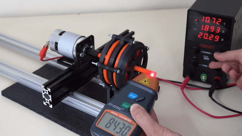
In operation, which the video below demonstrates nicely, the magnetic flux is coupled between the rotors by the steel inserts in the stator so that when one rotor moves, the other moves at a 4:1 (or 1:4) ratio in the opposite direction. [Retsetman] got the gearbox cranked up to about 8,500 RPM briefly, but found that extended operation at as little as 4,000 RPM invited disaster not due to eddy current heating of the inserts or magnets as one might expect, but from simple frictional heating of the rotor bearings.
Torque tests of the original gearbox were unimpressive, but [Retsetman]’s experiments with both laminated stator inserts and more powerful magnets really boosted the output — up to a 250% improvement! We’d also like to see what effect a Halbach array would have on performance, although we suspect that the proper ratios between the two rotors might be difficult to achieve.


Well have you seen a non 3dprinted one?
And it’s sort of in the article that it’s an enabler, you could of course make the same thing with a spoon and a log of wood but it’s simply simpler with 3d printing.
And because it’s simpler, people actually try it, and this is commonly called enabling.
You’re a better man than I. I usually just call those guys entitled grumpy aholes.
An unnecessarily critical reading. Making them at home is very uncommon despite the concept being quite old. Most people don’t have the manufacturing capability for the old methods, so yes this enables a new look at a possibly underutilized technology that may have widespread applications.
LOTS of videos on YouTube of magnetic gear boxes of all varieties, and almost all use 3D printed casements.
Classic gearboxes create a lot of harmful microplastic or chromium dust (depending on gear material) during they’re operation. If we could replace them with open source non-contact transmission systems it could create an entire new environment for development of sustainable transport modes.
The only problem I foresee with magnetic gears is also what makes them useful. The ability to simply slip past each other at high enough torque can be an issue if it does so at too low a torque. Now obviously you would design for the intended use case and build with a certain torque load in mind, but we’ve known about magnetic gears for a while and yet we don’t use them anywhere that’s meaningful. That’s leads me to suspect my concerns about the low torque issue is a bigger problem than the friction reduction/wear and tear. In a traditional gearbox the amount of torque that can be sustained is a function of the materials strength. In our magnetic gearbox you might quickly find you can’t engineer magnetic fields strong enough to handle the load of say a car parked on a hill without being overly large and heavy compared to it’s standard counterpart. You might say you would use a traditional parking brake in this case, but that’s ignoring the fact that if it can’t hold it in place then it certainly can’t push it up the hill either.
I really like this idea, but outside of uses were the low torque is a plus, I’m struggling to find a use case that wouldn’t be too much of a load without the gear box getting too big.
Most gearboxes especially those sized for ‘sustainable transport’ of anything bigger than ants are sealed units filled with a grease or oil – whatever micro wear particles get generated are contained, captive in that lubricant until they get taken up by the filter or disposed of properly along with the old lubricant as it changes. And many electric vehicles don’t even bother with a gearbox at all – the torque curve of the motor is so good it can have direct drive for the smaller vehicles and still work great from a standstill, though bigger vehicles probably still have some gearing.
The issue isn’t that they create particulates, as that should be nearly entirely a nonissue with responsible servicing and even if you assume the worst it is still a tiny problem compared to the tyre wear, brake wear, clothing fibre etc. The only thing that really makes a magnetic coupling gearbox stand out is you can expect a longer service life with less maintenance, and the maintenance is hopefully just a simple to access externally bearing replacement, which is a good thing. However when most gearbox will last decade after decade with pretty minimal maintenance already it is a rather limited gain in most situations.
Don’t get me wrong though, it is a cool concept that no doubt can be really useful sometimes. It just is far from a magic bullet that bests simple mechanical meshing gears in most situations.
If you think replacing zillions of transmission system with neodymium is going to be environmentally friendly then you don’t know about the mining that is done to get neodymium.
Also, regular neodymium magnets cant be used for this, has to be Type EH or preferably AH.
3D printing a means for rapid prototyping with oddly shaped components that would otherwise be difficult to make at home. Why is that so hard to understand?
This is really neat! Now instead of being a bit like a clutch that disengages safely on overload, it also has a gear ratio. Of course, a fixed step-down or step-up can be done very well with the non-magnetic parts of a machine when you need to, so this thing is still mainly about being non-contact and safe to overload just like the first one. Shouldn’t transmit as much vibration thru as gears do, sudden stops will not shock the other side of the coupling, and of course only the bearings are wearing physically as the creator points out.
The more interesting magnetic coupling to me is an asynchronous one. Induction motors which use an inner rotor and an outer stator with coils that are energized in sequence to produce a rotating magnetic field are useful, because for one input frequency, they vary their speed and torque to match a load within a certain design range. If the load is harder to turn, they slow down a bit but produce more torque, and if the load disappears they reach a certain limiting rpm and stop accelerating. If designed to tolerate a stall, they can produce a certain minimum torque at 0 rpm, decided by their design parameters but a large fraction of their maximum torque. Their torque curves also scale with input frequency; if you provide a slower input the output speeds are slower too. I bring this up because generating a rotating magnetic field by electric coils in a stator is not really conceptually different from using permanent magnets in an outer rotor to do it, making an uncommon but interesting kind of magnetic coupling. That makes them into something a bit like an automatic non-contact continuously variable transmission, no?
The locomotives hauling sugar cane in my area use magnetic coupling brake wagons.
When I did my apprenticeship many years ago, the mill used them prior to modern VF drives.
Maybe use a written-pole (Roesel) generator.
https://cordis.europa.eu/project/id/JOUR0086