Are your Eurorack modules too crowded? Sick of your patch cables making it hard to twiddle your knobs? Then you might be very interested in the new Euroknob, the knob that sports a hidden patch cable jack.
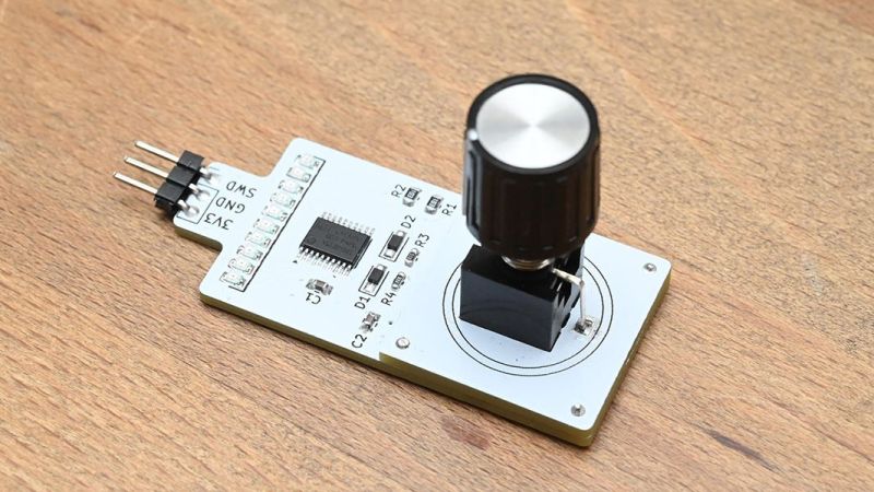
Honestly, when we first saw the Euroknob demo board, we thought [Mitxela] had gone a little off the rails. It looks like nothing more than a PCB-mount potentiometer or perhaps an encoder with a knob attached. Twist the knob and a row of LEDs on the board light up in sequence. Nice, but not exactly what we’re used to seeing from him. But then he popped the knob off the board, revealing that what we thought was the pot body is actually a 3.5-mm audio jack, and that the knob was attached to a mating plug that acts as an axle.
The kicker is that underneath the audio jack is an AS5600 magnetic encoder, and hidden in a slot milled in the tip of the audio jack is a tiny magnet. Pop the knob into the jack, give it a twist, and you’ve got manual control of your module. Take the knob out, plug in a patch cable, and you can let a control voltage from another module do the job. Genius!
To make it all work mechanically, [Mitxela] had to sandwich a spacer board on top of the main PCB. The spacer has a large cutout to make room for the sensor chip so the magnet can rotate without hitting anything. He also added a CH32V003 to run the encoder and drive the LEDs to provide feedback for the knob-jack. The video below has a brief demo.
This is just a proof of concept, to be sure, but it’s still pretty slick. Almost as slick as [Mitxela]’s recent fluid-motion simulation pendant, or his dual-wielding soldering irons.


brillant hack, through I share his durability worries…
I completely agree! Really cool concept! I think the lack of precision due to the trailing cable would drive me crazy.
If I understood correctly, the spin control only works when the special jacknob is used.
As soon as something else is plugged, the voltage it provides is used to control the parameter.
Haha… Jacknob
I’m more worried about losing the knobs. The sock gnomes are going to love them.
They have a magnet, so if you have a strip of steel nearby, problem solved!
The magnets used for the AS5600 are not very strong. I would probably just make a panel with some spare jacks to hold the knobs.
Does it have a inverse logic version ‘EURNOTAKNOB’ ?
Cool hack. Could use a stereo jack instead, that way a button could be added to the knob to change mode or another secondary function could be added.
It could use 1-Wire, where it’s power and signal on the same wire and the other is ground.
It’s against good UI design practice though.
Knobs and sliders should indicate their value by their positions. It’s no longer possible for the indicator to point at the value of the knob in each mode, because that would make the value jump every time you switch modes. It’s also difficult to press the button without twisting the knob at the same time.
I.e. why just about every digital oscilloscope has a bad user interface. Changing settings with a twisty push button always ends up in “oops, not that one…. oop, not that one either!”.
In the demonstration video, the knob is unmarked, and the value is displayed on an LED bargraph.
The knob position is marked with a white line, and the LED is there to indicate the level when the knob is disconnected.
Of course, because it’s programmable, you could change this (and he talks about doing this in the video, making it a multi-turn fine tune knob) but the behavior he shows is very much mapping the indicator mark on the knob to an absolute position.
He mentions different modes could be obtained by using stronger or weaker magnets, since the encoder chip also gives a field strength.
@hackaday: As Youtube is now guessing which automatically translated annoying machine language I “want” to listen too, is there a way for you to enable the option to switch the embedded video back to its original language? Or do I always have to go to Youtube and watch it there and change the language settings?
Oh I know! Are you really asking us how to stop Google from AI-ing, though? I only wish we had that kinda clout.
Anyway, they know what’s best for you, better than you do. Are you saying that you don’t love Little Brother? :)
This is a cool idea, and perhaps this is the right way to do it if you want a free-spinning encoder.
Since it’s usually going to control a parameter with a finite range, though (as that’s what a CV jack does), it might make more sense to put a potentiometer inside the knob instead. Then you’d add a pin that fits into a second hole to give the knob something to spin against, and line it up with markings on the panel. And you could also use that pin to supply a reference voltage for the pot.
I feel like I’ve seen audio devices that build a 3.5mm jack into the knob for a similar reason, but this is better. It would be cool if it became a standard.
You’re over-engineering it. If you want to limit the rotation of the knob, just [use Mitxela’s approach and] have a pin in the panel that sticks up into the bottom of the knob, and have a C-shaped track cut into the bottom of the knob for the pin, limiting the rotation.
Yeah that’s what I’m saying, except that if you use a pot it limits its own rotation, and it always matches the setting it points to physically.
I don’t think it’s any harder to put the potentiometer inside the knob, at least if you don’t mind making it a bit bigger
“Eurojack” was taken?
“Euroknob” is way funnier
Perhaps knobs could be stackable.
Hall effect sensors are pretty small.
If four pin jacks were used, they could be daisy chained like an LED strip. With different functions per level, course, fine, display, input, rotary encoder, input button, etc. Maybe with a larger wheel progressing to smaller and smaller knobs, in a step pyramid design.
Here’s my $0.04 (import tariffs already applied):
Put the encoder IC on the back of the PCB. The sensitivity should be high enough, and then you don’t need the spacer PCB.
Use two different sizes of magnets: one as shown in the video, and one that is slightly wider and sticks out to one side. The larger one mechanically limits the rotational angle by bumping into the contact inside the jack. The encoder IC can detect the different magnet strengths so it knows whether it is a single turn or multi turn knob.
Use a small and cheap (8 pin) MCU that reads the encoder IC and gives out a PWM signal with a RC filter. One extra pin could be used to send a signal to an addressable LED ring. This way every jack is a complete unit.
Use a TRS jack and a TRS plug for the knob. Normal patch cables for modular synths are only TS. The electrical connection of the ring and sleeve pins (or lack thereof) can be used to control a single channel analog switch IC that routes either the signal from the tip or the analog output from the MCU to the underlying circuit.
Yeah but it is a knob with a brain so there is something to go wrong there that will require some sort of magical jumpering of pins, esoteric generic FLASHHONGKONGNOVIRUS.exe to spend all saturday trying to get it respond to serial just to have it not recognize said copypasta linux bork string etc. I probably left out a couple of old man ranty bits in there, but I would have been fine with a pot, knob and an optoisolator with a gumstick batt It is cool looking I will give it that, just have had too much overengineered things go crazy because they could and that is usually how I get these kind of things by finding broken ones and fixing them or all saturday unbricking them lol. Anyway not to poop on OPs work because it is a cool bit and I definitely think quite a few eurorack folks will indeed want this :)
The knob module could also be a remote knob plugged in and on the end of a cable. Knobdongle. These could also be modular to take them off the rack and onto the desktop and could be grouped. I talk better in pictures if that would better describe what I’m thinking.