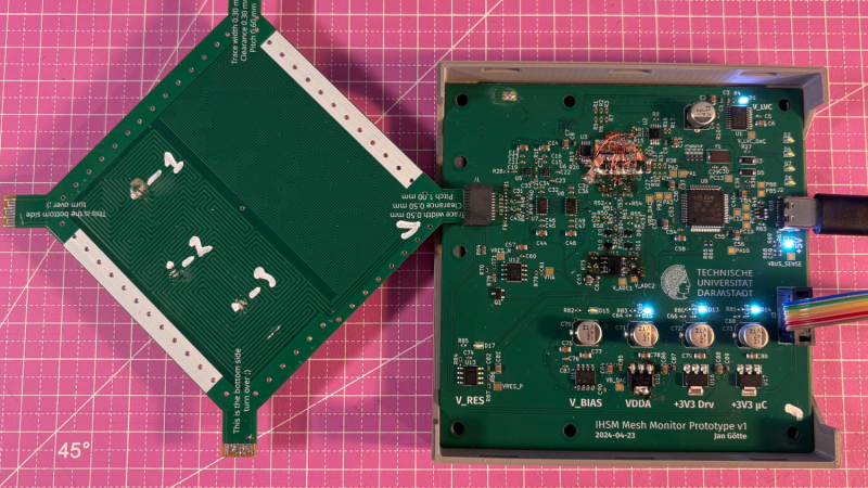
For certain high-security devices, such as card readers, ATMs, and hardware security modules, normal physical security isn’t enough – they need to wipe out their sensitive data if someone starts drilling through the case. Such devices, therefore, often integrate circuit meshes into their cases and regularly monitor them for changes that could indicate damage. To improve the sensitivity and accuracy of such countermeasures, [Jan Sebastian Götte] and [Björn Scheuermann] recently designed a time-domain reflectometer to monitor meshes (pre-print paper).
Many meshes are made from flexible circuit boards with winding traces built into the case, so cutting or drilling into the case breaks a trace. The problem is that most common ways to detect broken traces, such as by resistance or capacitance measurements, aren’t easy to implement with both high sensitivity and low error rates. Instead, this system uses time-domain reflectometry: it sends a sharp pulse into the mesh, then times the returning echoes to create a mesh fingerprint. When the circuit is damaged, it creates an additional echo, which is detected by classifier software. If enough subsequent measurements find a significant fingerprint change, it triggers a data wipe.
The most novel aspect of this design is its affordability. An STM32G4-series microcontroller manages the timing, pulse generation, and measurement, thanks to its two fast ADCs and a high-resolution timer with sub-200 picosecond resolution. For a pulse-shaping amplifier, [Jan] and [Björn] used the high-speed amplifiers in an HDMI redriver chip, which would normally compensate for cable and connector losses. Despite its inexpensive design, the circuit was sensitive enough to detect when oscilloscope probes contacted the trace, pick up temperature changes, and even discern the tiny variations between different copies of the same mesh.
It’s not absolutely impossible for an attacker to bypass this system, nor was it intended to be, but overcoming it would take a great deal of skill and some custom equipment, such as a non-conductive drill bit. If you’re interested in seeing such a system in the real world, check out this teardown of a payment terminal. One of the same authors also previously wrote a KiCad plugin to generate anti-tamper meshes.
Thanks to [mark999] for the tip!


I wonder what a diode laser engraver would do against it. Theoretically it could burn away the plastic until the traces are visible, which should make bypassing a lot easier. Youtube is full of videos where lasers are used to ablate away chip casing and the leadframe usually survives.
Though with modern microcontrollers having integrated fallback clocks etc, it’s not clear what you would do once you get a small hole into the enclosure. If you short out the battery, the SRAM contents will stay for a few seconds, but you won’t get into them without causing a power-on reset..
If you bypass the grid, you will trigger the detector. any change in geometry will change the pattern of returned echoes. That makes this approach significantly more robust than merely measuring total resistance or capacitance.
It actually might be wise to place a grounded shield over the grid just to prevent false detection from nearby fingers. Of course, that means that if you cut away any part of the shield the impedance of the grid will change in that spot, and again, trigger a detection.
It’s likely the device has a metal shell for protection anyways which would act like a shield.
This likely has other applications, like in a DIY TDR for testing cable runs, or in building a sonar and maybe even lidar unit. Maybe other kinds of test equipment too, like an oscilloscope or VNA.
Make an airtight enclosure, fill it up with pressurized nitrogen, and get a pressure sensor inside. Anything that damages the case will make the pressure drop, triggering the wipe.
30 PSI of nitrogen is enough to be above atmospheric pressure and will account for temperature differences. If the pressure drops by 10 PSI or more, wipe everything.
That would be pretty easy to bypass, just manipulate the device inside a pressure chamber.
It’s not easy as it sounds: you would need to know the pressure inside the device first.
“make an airtight enclosure”
just pot it.
You’re near enough going to have to do something similar if you want to make a cost effective, consumer-rugged device with any form of physical I/O.
Wouldn’t this cause an EMI problem with the constant repetitive fast edges and long meandering traces?
They can be very low power and don’t need to be very often to spot a change.
I’ve never gotten into tamper evident electronics beyond alarm systems, as it’s not easy to get the devices to tinker with. Or you can only attempt to bypass them just once. This project could enable research in these mechanisms.
As for any security mechanism, it is a skill check. Where better security requires higher skilled attackers, with more time, fancier equipment, and higher motivation. The idea of a nonconductive drill is nice, but I think you just need smaller ones. 0.1 mm will do you fine for this work, I expect.
“achieves both time resolution and rise time better than 200 ps—a 25 × improvement over previous work”
That’s funny, my TDR already achieved both better 5 years ago (and loxodes’s TDR was even better before me, but was more expensive [not to mention all the Tektronix and other stuff which was way ahead even in 80s]). But to be fair, he cited me as [33] :)
To offer some rectification to the diode sampling issue if anyone is interested (“In contrast to prior work [33, 14], we
precisely control the timing of our ADC and avoid the need for a second sampling stage.”), the two samplers were needed as the first sampler had about 1 pF storage capacitor (MOSFET gate) to minimize loading of the sampler and the second one to minimize droop. The ADC was directly triggered by sampling pulses, but you still can’t trust in how many clock cycles it will actually do what you want.
Having seen OTDR’s in action for fault finding 20+ years ago I can imagine this would be very sensitive – back then a portable OTDR could show you every joint and bend in a fibre that was kilometres long, one of the guys running it showed me the graph changing “live” as he gently bent the fibre with his fingers, and you could watch the steps/spikes change as a connector was mated or removed.