Water wells are simple things, but that doesn’t mean they are maintenance-free. It can be important to monitor water levels in a well, and that gets complicated when the well is remote. Commercial solutions exist, of course, but tend to be expensive and even impractical in some cases. That’s where [Hans Gaensbauer]’s low-cost, buoyancy-based well monitor comes in. An Engineers Without Border project, it not only cleverly measures water level in a simple way — logging to a text file on a USB stick in the process — but it’s so low-power that a single battery can run it for years.
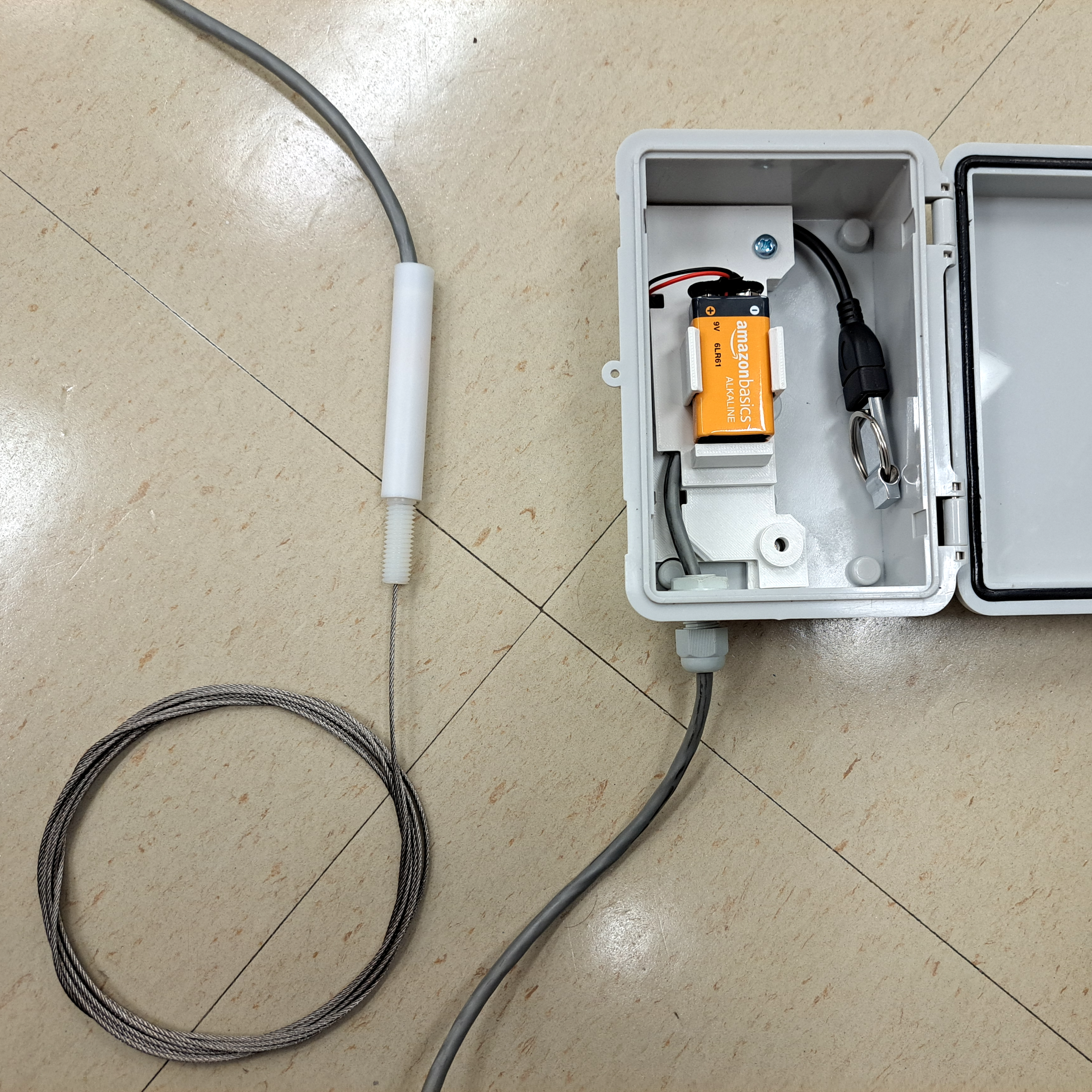
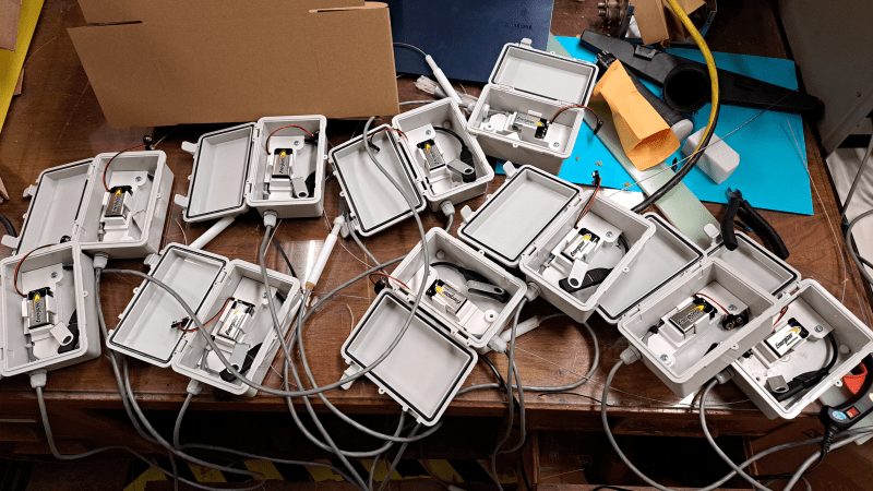
The monitor [Hans] designed works in the following way: suspend a length of pipe inside the well, and attach that pipe to a load cell. The apparent weight of the pipe will be directly proportional to how much of the pipe is above water. The fuller the well, the less the pipe will seem to weigh. It’s very clever, requires nothing to be in the well that isn’t already water-safe, and was designed so that the electronics sit outside in a weatherproof enclosure. Cost comes out to about $25 each, which compares pretty favorably to the $1000+ range of industrial sensors.
The concept is clever, but it took more that that to create a workable solution. For one thing, space was an issue. The entire well cap was only six inches in diameter, most of which was already occupied. [Hans] figured he had only about an inch to work with, but he made it work by designing a custom load cell out of a piece of aluminum with four strain gauges bonded to it. The resulting sensor is narrow, and sits within a nylon and PTFE tube that mounts vertically to the top of the well cap. Out from the bottom comes a steel cable that attaches to the submerged tube, and out the top comes a cable that brings the signals to the rest of the electronics in a separate enclosure. More details on the well monitor are in the project’s GitHub repository.
All one has to do after it’s installed is swap out the USB stick to retrieve readings, and every once in a long while change the battery. It sure beats taking manual sensor readings constantly, like meteorologists did back in WWII.


Hmmm…. picture caption says ” submerged pipe, ” but that would never change weight. Must be partially submerged….
And the steel cable is presumably of the stainless variety…
Mind you, even the source site doesn’t explicitly say partially submerged. .
Any fully submerged pipe becomes partially submerged if the water level gets low enough.
This might be easier to understand/build.
https://www.instructables.com/Water-Depth-Sensor-Based-on-Archimedes-Principle/
It works the same way, but from an anchor at the bottom (e.g. pavement tile) and also needs the partially submerged cylinder to measure the force.
Hmmm…. picture caption says ” submerged pipe, ” but that would never change weight. Must be partially submerged….
And the steel cable is presumably of the stainless variety…
Mind you, even the source site doesn’t explicitly say partially submerged. .
I’ve been trying to figure out a good way of doing exactly this for a long time. This is a pretty good idea. My only concern is that if the tube doesn’t hang quite straight then friction between it, the walls of the tube and the other things running the length of the well will dominate over the buoyancy of the pipe.
The tube never moves, you’re only measuring it’s apparent weight. Because of this you won’t see friction (a force that acts on objects moving against each other) enter the situation. Only if the bounancy force becomes so extreme as to bend the tube’s supports does this become an issue, and then you’ve got other problems.
Of course the tube moves: It’s suspended from a load cell. That’s how a load cell works: it measures the deformation in its strain gauge to determine the force applied to it.
Heck, it’s right in the name: strain is by definition movement.
Not dissing the author, but “professional” grade water level sensors do not cost USD 1000+! Examples: STS around EUR 400, Keller about EUR 250, Wika about EUR 200 and Benxu about EUR 90. They all use 4-20 mA output.
Which is still expensive especially if you need multiple units
You’re paying for more than just the sensor. This replaces the sensor itself and the entire upstream instrumentation system that reads your 20 mA current loop.
From my reading the author may be including additional deployment costs (e.g. installation, support materials like potting) in the cost? Maybe they will see this and jump in with some insights.
Good info @alloydog
I made something like that years ago ,it works, but not for years , first of all :loadcells need calibration rather often because they drift , second: a weight submersed in water will attract dirt and thereby buoyancy will change over time and third: as TOm says, the least friction will spoil the reading ,but if you overcome this, its smart because, if the partly submersed rod at a given height has a geometri with a known relation to the well at same height you can from the displaced weight , calculate the weight(amount) of the liquid in the well(container) and it would even work with pressurized gases .
I doubt the drift will be large enough to matter. A coarse reading that’s 20% off is probably good enough. Friction doesn’t enter the situation in an essentially fully static system that measures buoyant force, see my above comment.
the friction WILL make a problem. imagine the extreme: the steel cable stuck or anchored in the middle. the change of buoyancy force transferred by the cable will be stopped at this point.
If the weight is steel, then full scale is 87% ie 13% change. Unless your weights are matched to the load cell full scale range, then it is less. e.g. if the weight is 10% of load cell full scale, then the maximum change will only be 1.3% of load cell full scale.
Now if you said that the objective was 5% accuracy of water depth, then we are down to 0.07% of load cell.
Long term drift and temperature coefficients are likely to matter.
I think attaching a simple quarter-inch metal rod to the load cell ought to work as well. Buoyant forces don’t just apply to things that are hollow.
Yep. A round rod or a long metal profile would work as well.
If you are working on a water system, though, you quite likely have a spare length of water pipe that is known good for use in drinking water. Cut a piece, hang it in place.
I’m now wondering if you put a T fitting on the water pipe with a (sealed) speaker closing the open end if you could use sound up the water pipe to the house to send the data. Get rid of the thumb drive, only walk out to replace batteries.
You can indeed use resonant frequency, pulse delay and various other acoustic techniques. However they are all very sensitive to temperature, atmospheric pressure and humidity.
So not inherently calibrated or accurate.
It can however be incredibly cheap when you have a sound card inside your system for free. I have used acoustic tricks to measure air pressure, temperature, humidity, windspeed and direction, and rainfall. The only “special” hardware beyond microphones/speakers, was various tubes and cavities. It worked fairly well, (not very well), and had an awful lot of compensations to get there. A lot of fun ingenuity, so I’d recommend it.
Where can someone who knows some optics and general science learn about acoustics from the perspective of designing things like this?
Hi – check out this Youtube – you will not want for much more… This time with the link: https://www.youtube.com/watch?v=2MF1FCjottk
This assumes the well is straight and perfectly vertical.
Our 220′ deep well most assuredly was not. That suspended pipe would strike the sides at least once along the way, introducing at least bias and/or hysteresis in the measurement, but probably making it just a random number generator.
I use this https://www.amazon.com/dp/B0DRNKWRZ2?ref=fed_asin_title thing in a tank, it ultrasonically bounces off the water. Might work in a well. Works with Tuya/Smart Life so I have it lighting a smart bulb green at 8am for 1 hr if “OK”, red for 3 hrs (so I notice) if “low”. $53 is more than $25, but far less than 1k.
Even cheaper from Ali.
Unfortunately it doesn’t work in a well; I tried! The ultrasonic things work at around 40kHz; but in a typical artesian well (mine is ~120 feet deep) the dispersion due to path length differences means that no signal actually comes back. I’ve done some initial tests and found that it might work if I used a chirp from ~100Hz to 1kHz.
I would have loved more details about the design choices made versus the constraints (I suppose price, reliability, and ease of use were involved, possibly in that order).
I assume the chip was selected for its low cost, but it might have been great to have one that could be flashed from USB. Similarly, an auto-calibrating algorithm could have been defined, or a calibration helper using the LED to assist during installation. That LED could also be used for troubleshooting or confirming everything is OK, coupled with two pads that can be shorted with a screwdriver, for example to produce an output to the drive every 20 seconds instead of every 3 hours. Useful during installation.
“Cost comes out to about $25 each”
Does that include the cost of the pipe hanging down the well? Probably not, judging from the price I paid for the 100′ spool I bought recently.
Though I’m pretty impressed he got the cost for a weatherproof enclosure, cable gland, and all the electronics and cables down to $25 in qty 10. Especially including custom cardboard packaging.
I’d be interested in finding out the process in getting custom cardboard packaging designed and produced, actually…
The concerns about hydrostatic sensors in the article sound a bit weird. Wouldn’t they be solved by using an air pipe to the bottom instead? Then all electronics and the pressure sensor could be above surface. No pressure reference is needed either, just measure against ambient pressure.
Add a valve to the air pipe and you can clear any clogs with a bike pump.
It won’t just be clogs that need more air, the water will tend to rise up the tube as air dissolves in it, also temperature cycling will lead to air loss. There are bubbler units with a pump but that takes a lot more energy.
NOAA for some of their tide gauges use a tube with a weighted open end submerged (I think protected in a pipe) and pump a small amount of air into the tube to clear the tube of water than measure the air pressure and the height of the water above the open end of the tube can be calculated.
Couldn’t you make an even simpler water level monitor with two insulated wires and a circuit to measure the capacitance between them? Water and air have different dielectric constants.
Yup. Winding the two wires around a plastic rod increases the effect. I’ve seen a copper pipe with a wire suspended down the middle. Never tried either.
Anther method is you take a plastic pipe and put two strips of copper tape om the outside, then cover that with some sort of waterproof insulation (heatshink with glue works).
Response isn’t quite linear (but close enough) so take that into when calibrating. A simple conversion table works.
I’ve had this setup in a water tank for about 20 years. I got the idea from the Parallex website, but can’t find the page now.
A friend uses the capacitance method for his fuel and water tanks on his boat, he put copper tape on the outside of his nonmetallic tanks and a micro-computer and display
For a well level – would the steel liner etc. be a problem?
How about a ruler and a web camera?
Hi Joel,
The reason is usually power and data budget for the device. Also, most web cams will enter power save mode after a time, or burn cpu cycles if missing a built in h264 or mjpeg hardware codec.
The other reason is surfaces become quickly covered in algae or shmoo if exposed to light.
The best industrial level sensors are radar based depth type, as they still operate in rain, dust, and snow.
the weight version of gwr, guided wave radar.
If you need an on-off solution, a floating pole with a magnet on top and a reed relay that triggers when the magnet gets close is enough.