It’s one thing to learn about transmission lines in theory, and quite another to watch a voltage pulse bounce off an open connector. [Alpha Phoenix] bridges the gap between knowledge and understanding in the excellent videos after the break. With a simple circuit, he uses an oscilloscope to visualize the propagation of electricity, showing us exactly how signals travel, reflect, and interfere.
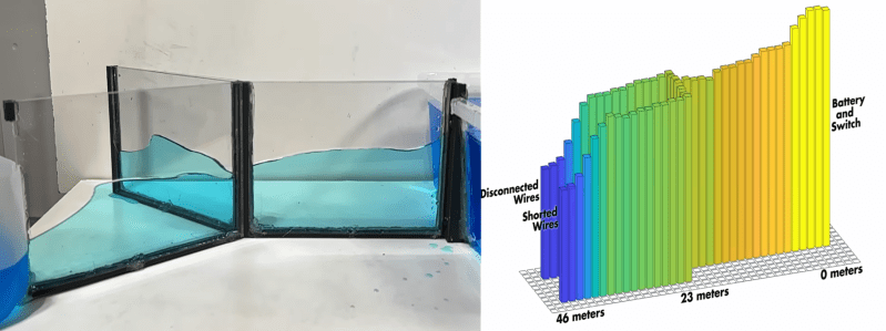
The experiment relies on a twisted-pair Y-harness, where one leg is left open and the other is terminated by a resistor. By stitching together oscilloscope traces captured at regular intervals along the wire, [Alpha Phoenix] constructs a visualization of the voltage pulse propagating. To make this intuitive, [Alpha Phoenix] built a water model of the same circuit with acrylic channels, and the visual result is almost identical to the electrical traces.
For those who dabble in the dark art of RF and radio, the real payoff is the demonstration of impedance matching in the second video. He swaps resistors on the terminated leg to show how energy “sloshes” back when the resistance is too high or too low. However, when the resistor matches the line’s characteristic impedance, the reflection vanishes entirely—the energy is perfectly dissipated. It really makes it click how a well-matched, low SWR antenna is crucial for performance and protecting your radio.
[Alpha Phoenix] is a genius at making physics visible. He even managed “film” a laser beam traveling at light speed.


I found it odd he didn’t diagram the electric circuit better. Those twisted pair “wires” are literally a series of inductors and capacitors and that’s really what’s causing the delays and wave actions. The capacitance is storing the charges as the voltage wants to change while the inductance is opposing the change in flow of the charge. So it take some time for all the capacitance and inductance to settle out.
The impedance he is matching is that of the power supply. Matching impedance is important to maximize power transmission. He could have just asked a ham radio operator about SWR (standing wave ratio).
These twisted wire are not “literally a series of inductors and capacitors”. They can be treated as such, which is called “lumped elements equivalent”, and this is just an analytical tool, it’s not the essence of the phenomenon.
What happens in reality is that an EM-wave (a wavefront) propagates within the boundaries of the transmission line. Same happens along a waveguide. The only difference is the wave propagation mode.
Correction: “lumped elements equivalent” should be read as “chain of lumped element equivalents”, which is a stupid way to say “distributed elements model”. Seems like I write bull*** when haven’t got my coffee for the morning.
The wave behavior and the two end points are the same as a wave in a rope. One end is the rope tied to the wall. The other one is the rope tied to a ring that can slide freely up and down. One has an inverted reflection and the other does not.
This is a good place to talk about the “boundary conditions” and push back on the ill defined/undefined “corner case” and “edge case” that have diffused into technical descriptions over the last decade. These are boundary conditions. The constraints at the boundaries. You use them with the differential equations and the physical explanations so that people can know precisely what you mean. It would be nice if the terms of the last 200 or 300 years were not so suddenly abandoned for fuzzy language. I had assumed people use the -case wordings, use case edge case corner case because they are uncertain about what they are describing and don’t want to be pinned down over details. But now I think they just don’t know the math or the history of thinking about these problems and communicating ideas clearly to contemporaries.
Agreed. I used to use “edge-case” quite frequently before studying calculus. The thing is, we are also peer pressured into using that kind of wording. I have to refrain from using “boundary condition” in quite a lot of settings as it’s not really well accepted even by supposedly technical people and colleagues. They either look at me like I’m a stuck-up math geek or a pretentious arrogant who fakes intellect with big words.
I believe it all comes down to how Math as a subject has been getting further and further abstract and complex over the last couple hundred years, effectively making it harder and harder for educators to ground its understanding in reality. There’s maybe a handful of really great teachers who can make students link math concepts to real world phenomena; most people are instead stuck with learning Math as a completely abstract subject with rules and labels fully self-contained.
Well said sir, so how would you define the boundary conditions of said rope or transmission line what have you? I understand what Google is I’m just curious to hear how you’d describe them
Great illustration, thanks for sharing! I myself prefer it when they explain how things work, rather than (or besides) proving it with formulas, which is what they usually do when teaching scientific stuff. But this particular explanation seems to have taken a lot of effort to research and make as intuitive as it is.
“They sold this cable to me as 50 ohms, and it’s not!”
No dude, they sold you a piece of coaxial cable with 50 ohms characteristic impedance. Which also means it’s a complex number, not just something that you measure with the multimeter… (unless it’s a Nano VNA, hehe).
Here is the reference video of wave behaviour, regardless of whether it is optical, electrical or mechanical waves. If you ever struggled understanding impedance matching, allocate 30 minutes of focus time and enjoy: https://youtu.be/DovunOxlY1k?si=wLDyt2MyMDmIh9s8&t=102