A time domain reflectometer (TDR) is a useful tool to have for finding faults in a wiring harness. However, they don’t come cheap, putting them out of reach for many shadetree mechanics that like to work on their own cars. However, [László SZŐKE] has been exploring a neat way to build a similar device on the cheap.
Typically, time domain reflectometry involves shooting a short electric pulse down a wire, and listening for how long it takes to bounce back. The time depends on the length of the wire, so it can be used to determine the location of a break in conductivity. Unfortunately, these pulses move so fast that very fast, very expensive hardware is needed to make these measurements.
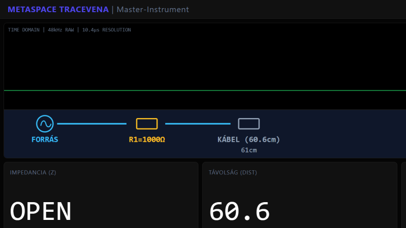
[László’s] technique relies on lower-tech hardware. Instead of sending a very short pulse down a wire, his rig uses a cheap C-Media USB audio device to send a 4 kHz or 8 kHz sine wave instead. Then, by listening to the reflection and measuring the phase shift, it’s possible to detect the distance to the end of the wire (or a break along its length). Some supporting hardware is required for protection’s sake, and to tune the setup for measuring shorter or longer cabling. However, with some smart software processing, [László] states that it’s possible to measure down to 1 cm resolution.
The idea is that this setup could prove particularly useful for automotive troubleshooting. If you measure a wire and the device reports a length of 30 cm, when you know the wire stretches several meters into the engine bay… you know there’s a break around 30 cm from your measurement point.
There’s still plenty of work to be done – for now, [László] is working on a new prototype that should have better performance when testing shorter cables. Still, we love to see this sort of out-of-the-box thinking put towards a common troubleshooting task. If you’re doing fun signal analysis work of your own, don’t hesitate to light up the tipsline.


So this is a phase-domain reflectometer then?
How does this compare to frequency domain reflectometry done with a cheap NanoVNA?
The link
https://hackaday.io/project/205619-turning-cheap-audio-chips-into-industrial-tdr
doesn’t work :-(
Not helpful reply, but it works for me.
If I understand correctly, this simply measures capacitance. So, you’ll need to calibrate it to each cable somehow. And accuracy after that will depend on how consistent the wire bundle is, as well as distance from ground (chassis)…
No, standing wave.
The descriptive text is a bit muddled (as is the diagram–D1/D2 are not “back to back”) But this is not a TDR, nor does is seem to use use “standing waves.” The op says:
“… The parasitic capacitance of the cable causes a minute phase shift in the sine wave…”
It looks like a capacitance meter, and @MD’s remarks would seem on point.
At 8 khz, by the way, wavelength is on the order of 37000 meters. Hard to imagine you’ll resolve centimeters using “standing waves” on commodity hardware under those conditions.
This looks awesome; I use a TDR almost every day troubleshooting POTS lines. Speaking from experience, even if the measurements/readings taken are only a ballpark figure, they can still be invaluable in troubleshooting
How expensive is very expensive? $70 network cable testers can do TDR now. Make a RJ45 breakout cable with croc clips to connect it.
I was thinking along those same lines. How much do the network TDR meters depend on the standard impedance, common mode rejection and such characteristics specified for network cabling?
A random wire embedded at a random, changing depth in a randomly sized/size changing bundle (un)terminated in random ways seems to me like it would be tougher to characterize than twisted pair or co-ax.
Thanks Gemini for the schematic.
The schematic looks very much “AI”-generated, the SPDT switch makes no sense at all (and some of the labels are also nonsense). I have a hard time believing that this approach can work without at the very least 1-2 quality opamps as a differential amplifier.
Ha, yeah, guess it’s a “janky” AI schematic (to use the author’s term). Also, “firewall”…seriously? Please don’t needlessly repurpose words. Esp. given there’s also a firewall in a car!!! I’m guessing English is the author’s 2nd language, so that explains some of the breathlessness of it ;-) No reason to believe this won’t work though, notwithstanding the calibration issues I pointed out above…and the schematic errors…
Just buy the cheapest NanoVNA (H version is around $40 from the “official” store) and you get a much more capable device that can also to TDR.