Screws are useful fasteners for 3D prints, but the effectiveness of a screw (not to mention the ease or hassle of insertion) depends on the hole itself. This comprehensive guide on how to design screw holes in 3D printed parts takes guesswork out by providing reference tables as well as useful general tips.
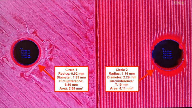
The guide provides handy tables saying exactly how big to design a hole depending on screw type, material (PLA, PETG, or high-flow PETG) and whether the hole is printed in a vertical or horizontal orientation. This takes the guesswork out of screw hole design.
The reason for different numbers is because multiple (but predictable) variables affect a 3D-printed hole’s final dimensions. Shrinkage, filament properties, and printing orientation can all measurably affect small features like screw holes; accounting for these is the difference between a good fit, and cracking or stripping.
In addition to the tables, there are loads of other useful tips. Designing lead-ins makes screws easier to insert and engage, and while increasing walls is an easy way to add strength it’s also possible to use 3D-printed microfeatures which are more resistant to distortion and don’t depend on slicer settings. There’s even suggested torque amounts for different screw and material types.
Sure, the most reliable way to get a hole of a known size is to drill it out yourself. But that’s an extra step, and drill bits aren’t always at hand in the desired sizes. The guide shows that it is entirely possible to print an ideal screw hole by taking a few variables into account.
If your design calls for screws, be sure to check it out and see if there’s anything you can use in your own designs.


Well, it’s reverse from what I would think. Vertical HOLE means that axis of the hole is vertical (axis right angle to bed), right? Here they mean that when SURFACE is right angle, it’s a hole in vertical surface, which makes it a vertical hole :/
Aahh… the first seeds of world wide confusion has been planted.
We’re screwed…
I love the sense of humor on the comments section! Makes my day!!
They rose to the occasion.
Great way to drive the point home, for sure.
No need to ratchet the tension on the poor commenter.
so.. essentially…
..we could drop a bit of sand down this horizontal hole,
by way of gravity..
right?
..!?
that is an interesting twist you gave it.
There’s also the way that doesn’t overcomplicate the design and give a strong result even with screws designed for metal:
– Draw the holes like you would for metal
– Print with enough perimeters to allow strong tightening
– Drill the size you would for metal, because holes are always smaller than expected and not smooth
– Hot mount the screws: heat up the screw with a lighter and screw while hot (easy with BTR screws).
– Chamfer / clean the hole entrance with a large drill bit
I found the result stronger than using cold mounted metal inserts.
If you print with more perimeters and then drill out the hole to size, you can as well just tap it properly then.
That said, for small-ish metal screws (M2.5 to M4 or so) that don’t see a lot of load (e.g. for holding on a lid or something of that matter), you can just screw them in and let them form their thread on their own. They will get rather warm due to all the friction, so you need to take care not to overtighten them lest they strip their thread immediately.
Or add a shim on both sides.
yeah i am closer to this technique, though i typically avoid plastic threads (though i make them sometimes on accident). i like the screw to go clean through and engage a nut on the other side. And i don’t always use screws, sometimes i use bits of wire (twist ties) and zip ties or dowels or whatever is clever for the use. but the point is, i definitely do not expect tight tolerances out of my 3d printer. i make everything 0.2mm too big and expect a friction fit but i’m never surprised to drill it out, especially if it’s smaller than about 5mm
“by accident”
I like the method Thomas Sanladerer put forward about a year ago in a video about this, see the self forming threads section. Pretty sure it was featured here, though I can’t seem to find it.
Essentially you size the hole for the screw without consideration for the thread, then have 3 ridges that run up the inside which give the screw something to bite on and also enough space for the deformed plastic to go. This is hard to describe well, but really easy to grasp when you see it. I use it anywhere that doesn’t warrant a threaded insert.
https://www.youtube.com/watch?v=HgEEtk85rAY
You can also go for slightly less than 50% thread engagement (hole diameter slightly higher than halfway between core and outer diameters).
I like that idea
Screws for wood construction make all of this less critical. They have tapered tips, they’re self-tapping, they have wide sharp threads. Hole sizes between ~1mm and ~4mm work with good strength for like a number 6 or 8 construction screw. And they’re locally available in quantity for low prices (homedepot/etc).
i’ve used drywall screws and found them to be pretty forgiving but i would expect the screws to split the plastic if the hole diameter is smaller than like 70% of the outer diameter of the threads. If it was any smaller than 3mm for a #8, i would expect it to crack up the plastic around it. I guess crumpled plastic is just part of the game?
I like melt-in brass inserts for most things. You can’t always use them due to space or access for installation but they hold well and are relatively cheap.
After trying all sorts of methods, heated screws, cutting threads, printing threads, letting the screw cut its own threads, I find that generally, I only get one assembly out of plastic threads. (I mainly use PETG, PCTG and PLA, no crazy strong engineering filaments) Meaning, if I have to take something apart again, I might as well reprint it because the threads will get destroyed and it will never hold tight.
For some applications a single use is fine but anything that may need to be disassembled and reassembled, I design for inserts with metal threads or through holes with nuts.
I have embedded hex nuts during prints, and square nuts when “sideways”,. Timing is critical, ample room is required, but no support features are.
For plastics
https://phys.org/news/2026-05-bottles-battery-acid-production-valuable.html