When [Denki Otaku] bought a ¥1,200 (roughly €6.5) XLR ground loop isolator off Japanese Amazon, he initially didn’t suspect that anything was off. Since they’re fairly simple devices, with basically a 1:1 transformer per channel in some kind of enclosure, the price wasn’t unreasonable.
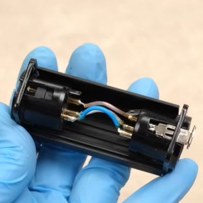
That’s before a teardown showed that this ‘ground loop isolator’ actually contains direct wiring between the XLR sockets, but that doesn’t mean that you cannot still make an educational video about the real devices.
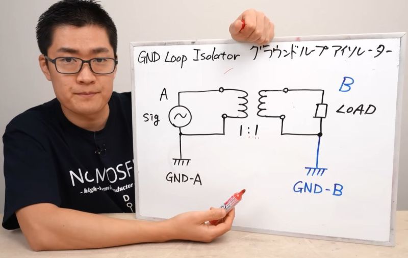
First the basic theory is explained, before the fake ground loop isolator is subjected to an analysis, showing why you’d want to use the real deal. Of course, detecting a fake one is pretty easy, as a simple continuity test with a multimeter or similar will show that DC passes right through the fake isolator.
Next a real ground loop isolator was designed with a custom PCB and a high-pass filter added to the feature list. Here rather than a very basic filter with cheapo parts there was definitely some gold-plating going on, but it does show what you can do in addition to just adding a few simple transformers for ground isolation purposes.
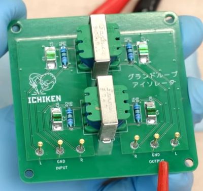 The finished ground loop isolator device is pretty large, and would definitely require a larger enclosure than the homeopathic device, but it makes for an easy test bed with convenient access during the subsequent analysis.
Here each of the two channels has its own transformer and filter, with an initial test just by ear making the injected 2 kHz noise signal appear to go completely away.
Next, an oscilloscope is used to visualize the functionality, with the non-isolated 440 Hz test signal first shown with and without the injected noise, showing the clear impact of the noise and subsequently the isolator.
Of course, high-frequency noises will still pass through the transformer via parasitic capacitance leakage between the windings, so it’s not a silver bullet. Here the analysis at the end of the video shows the noise-rejection characteristics of these isolators, and why adding a high-pass filter makes a lot of sense. Finally, the scam device’s XLR connectors were reused in an enclosure for this custom board, giving it some purpose after all.


With a symmetrical signal they could at least have omitted the ground pin connection, thereby making it a “ground lift” adapter. Then it’d at least have been theoretically useful.
A differential signal would not be disturbed by common mode noise, but wouldn’t that stress the input and output of the devices by moving the ground loop current there instead? I mean, if it’s designed for that, all is well, but if you’re trying to mod an audio device for a “floating” output by disconnecting the ground, the output has to absorb the current and the input of the receiving device must pass it.
In a differential/balanced circuit, there is ideally zero “ground” current and it is not ground referenced. All of the current should be differential between the + and -. There is no need for ground current to flow between devices- it should not. The connection only serves to create a continuous shield. There’s no electrical stress in breaking that ground. Most quality audio equipment will have a ground lift switch for this purpose. If there’s any significant current on the shield, you have other problems.
^ ^ This
Ground loop isolation just requires breaking a ground connection so there’s no longer a closed loop in which unwanted currents can circulate.
Full transformer isolation has its uses, but transformers are not required just to break ground loops.
That’s true, but here we’re assuming there is a ground current flowing between the devices that causes the need to “solve” the situation by disconnecting the shield ground between them. If my intuition is correct, this would simply shift the ground loop current into a common mode current in the differential pair.
For instance, in an older house with outlets grounded to neutral, a load on the circuit causes different outlets to have different ground voltages. If you connect a shielded cable from one device in one outlet to another across the room in a different outlet, you’ll see a little spark as the ground levels try to equalize.
I wonder what is the purpose of such a filtered ground loop isolator.
I don’t want mine to filter-out anything since I’m using it for audio.
It’s a cheap, and real, one, and is getting rid of any hum.
Without looking at the video I think the following line should tell you that:
“Of course, high-frequency noises will still pass through the transformer via parasitic capacitance leakage between the windings, so it’s not a silver bullet.”
But that’s not too relevant for just getting rid of a 50/60Hz hum of course.
we wanted iMug not iChicken 😭🙏
Aliexpress? Or is there a Japanese Amazon?
Seriously? Jeez, man. Take off your blinders.
https://www.amazon.co.jp/
It is very concerning the number of folks who think the U.S.A. is the
“center” of earth. We are just a small speck.
Considering Amazon is an American company, it seems plausible they wouldn’t have a foreign presence. …But I have purchased from amazon.jp, yes.
Unsurprisingly, said number approximates the population of Murica. There are very few of us here who are not geocentric, and for that I apologise :)
What the heck are you trying to say?
Geocentric? I would think that most human inhabitants of the 3d rock from the sun are prejudiced and favor the Earth over other planets.
Pop of America approximates Japan? I assume your reference is the USA. The US pop is approx 340 mil. Japan is about 123 mil.
No, the population of the US approximates “the number of folks who think the U.S.A. is the
‘center’ of earth”. As seen in the direct parent comment of the one you responded to.
That Muricans are mostly idiots and assume that the world (which might as well be flat) revolves around them. Source: Me. I live here.
You’re certainly an idiot dremu.
Looking just at nation-states by geography or population, the USA ranks near the top in both.
You are correct in one way: Looking just at nation-states by overall arrogance, the USA is near or at the top as well. North Korea and a few other dictatorships might give it some competition though depending on what day it is.
The US may have larger land mass and/or population than most countries, but it’s still a small speck in the overall global area / population. Any one country is. Even China and India each represent only a small(ish) percentage of humanity as a whole.
Amazon has a localized site for every country they do business in. The localized sites are in the country’s dominant language, with a selection for various translations. They also offer merchandise localised for the country.
I can’t get Irish malt vinegar on Amazon in Germany (amazon.de,) but Amazon in Ireland (amazon.ie) has malt vinegar from multiple manufacturers.
I can buy a specific model of Viatom/Wellue Bluetooth pulseoximeter from amazon.de, but the same model is not available on amazon.com – they offer a similar model that works the same, looks a bit different, meets slightly different standards, costs about the same, and stores data in the same format.
Yeah, amazon.jp is a thing, for real.
I would not be surprised if Amazon is more popular in Germany than in the US in percentage of the population using it.
There’s also an Amazon where I am, but I never used Amazon and I’m not interested in doing so.
Same for ebay incidentally, also an international thing, and they buy up local versions of companies offering similar service (dammit).
Fun fact, the same products with the same path are available on multiple country-specific sites.
For example, these all point to the same Creality PETG spools:
https://www.amazon.com/xyzzy/dp/B0D72GT1HF
https://www.amazon.co.uk/xyzzy/dp/B0D72GT1HF
andhttps://www.amazon.co.jp/xyzzy/dp/B0FFMTW8W7
There is a bit of an issue with the US having made shipping things to/from the US impossible though. You have to have out-of-US storage if you are a US company wanting to do trade internationally.
And the mad thing is that the EU mofos in Brussels are trying to emulate that idiocy.
Just to clarify – Aliexpress is Chinese (Shaolin monks, kung fu, Peking duck and Jackie Chan) not Japanese (Ninjas, ju-jitsu, sushi and Akira Kurosawa) ;-)
Btw, is there a hackaday for a KISS DIY isolated USB-Oscilloscope?
What specs do you need? How KISS do you want?
You could simply use a laptop audio input and something like SoundScope or one any number of similar programs, or write your own. Run it off batteries, don’t plug anything else into the USB ports, and it’s isolated.
Use the two stereo channels and get differential input.
Depending on your hardware and the software you can get bandwidths of 20-100 kHz. The low end is typically a few Hz, but you can mod the hardware to go to DC.
Yeah, isolated, i thought optocouplers or something. So you don’t fry your PC or hub accidentally. I hoped there’s cheap electrical voltage/ampere measurements chips around, you could expose as a Linux /dev/ file you can grep. Are there?
You’re going to need to decide on your specs a lot more before you can make any useful decisions about hardware. What bandwidth do you want? Does it need to go to DC? What input voltage range? How much isolation voltage do you need to withstand? Do you want differential input? What CMRR? What’s your budget?
Yes, you can go very cheap indeed — I’ve already suggested a zero-cost option. But you have to decide what you will give up to do that, and determine yourself whether that suits your needs.
Most halfway reasonable Multimeters with a data connection use optocouplers to transfer UART style 8n1/7n1/… measurement packets one-way, the PC side then either is a classic RS232 D-SUB9, or nowadays a Serial-to-USB chip molded into a USB connector.
For a real oscilloscope, use either Ethernet (which already has transformers on both device PHYs), or WiFi (e.g. newer Rigol scopes have it either built in, or come with drivers for Realtek8188 chipsets, i.e. you can use a cheap USB-Wifi adapter).
If you want to build something yourself, you may leverage e.g. an ESP32. There are plenty of fairly cheap ADCs you can connect to it (either via SPI, or if the audio range fits your needs, via I2S).
Uh, power it with a battery. Problem solved.
I’m really suprised at how much basic electronic knowledge is missing from a lot of HAD users. I struggle with the opposite. I am mostly clueless when it comes to firmware/software. Wish I’d learned it a long time ago.
Everybody starts somewhere.
Including you. It’s not too late.
Keep learning.
I learned electronics as an apprentice, down from bottom up. Yes, some solutions appear cringy to me, but I’m mostly pleased that people show interest and search for solutions. Hardcore diy electronics started to diminish two or three decades ago, and we learned that replacing a whole module is cheaper that fetching the solder iron.
But it’s less fun, isn’t it?
Let them post photo-realistic breadboard images instead of ISO schematics, two-page explanations about diodes and other wonders: I have no problems with that.
And let’s stay friendly and positive. If you know more you’re the senior, so your task might be enabling others.
When talking about production-grade ground-lifting (or DI-boxes), there’s a lot more to consider. I wouldn’t expect gold plated contacts, force-tested connectors and proper shielding from a 6$ Shenzhen toy. Use it as a doorstop. Nice story, though; Turns trash into something interesting.
Trying to send 2 channels isolated through a single XLR connector? That’s not how it works. You will need 5 conductors. There are 5 pin versions on a single plug/socket.
Yeah, there is that bit.