
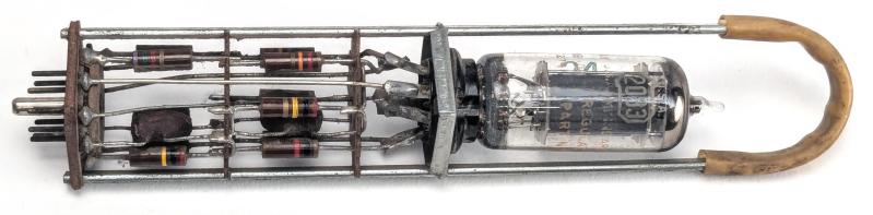
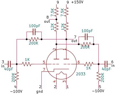
Taking a break from ogling microscopic features in Intel’s semiconductor processors, [Ken Shirriff] is back to instead poking at decidedly macroscopic pluggable modules from the 1948 IBM 604 Electronic Calculator. This time around it’s one of the so-called trigger modules in the form of the TR-3, which uses a flip-flop circuit to implement the timing signals and pulses that made the 604 work.
This differs from the thyratron module that we covered previously. A thyratron is a high current switch and rectifier, which is useful more for the periphery of the computer system. These TR-3s on the other hand were used to implement the basic logic circuits, even if a flip-flop by itself seems rather boring, being just a circuit that toggles between two states.
In this TR-3 module we find a 2033 dual triode design which thus increases density by having the two inverters of the flip-flop in the same tube. The rest of the module is taken up by the requisite capacitors and resistors that complete the circuit. After wiring up this original module, [Ken] was able to make it trigger somewhat reliably, requiring a stable input trigger.
Notable is that in the IBM 650 from 1954 this flip-flop circuit was abandoned in favor of one based on diode logic, presumably to use more reliable Boolean logic instead of the much fussier analog interactions. Naturally, in the first transistorized computers the use of diode-transistor logic (DTL) was exceedingly common, so this makes a lot of sense.












I bet there was nothing terrifying at all about having to debug a computer full of racks of thousands of these small scale gates where the switching level was swing by a couple of hundred volts.
No wonder everybody in the 50’s smoked all day and had three martini’s for lunch
The wore rubber-soled shoes and always kept one hand in their pocket. Standard practice around high voltage equipment.
Still goes through the heart?
Isn’t it ironic?
Use the back of your hand for DC.
[ Else your muscles will contract, clenching your hand around the conductor and you won’t be able to let go. ]
Schematic does not match the photo nor IBM 1958 docs; many gross errors. Sigh.
These had an insulated handle on them and I think no biggie to swap out. Installing one would be the danger.
2033 triode like a 6J6 but with reduced filament current. Matching was inportant, +/-2.5% resistors used as well.
“Schematic does not match the photo nor IBM 1958 docs; many gross errors. Sigh.”
Please elaborate.
Digging through 1958 IBM 604 Manual of Instruction, the TR-3 had a mod “note: one 20k instead used in later units” for the 12k and 7k5 (pg. 260) so no split plate resistors. This is what first had me questioning the reverse-engineering, as well as the “capacitive input trigger” which would glitch a lot compared to the many other FF types.
Sorry I am wrong about that, other triggers appear DC-coupled which would be a nightmare to maintain.
Ref. [url]https://archive.org/details/bitsavers_ibm6042277_27960715/page/n247/mode/2up[/url]
Digging through 1958 IBM 604 Manual of Instruction, the TR-3 “note: one 20k instead used in later units” for the 12k and 7k5 plate resistors (pg. 260). This is what I’d seen I think.
My earlier post did not get approved I guess. It had the Bitsavers URL for the 1958 IBM 604 Manual of Instruction. And my apology for the TR-3 “direct grid input trigger” which is different from the other 604 FF designs and susceptible to glitching, so I did not believe the schematic.
In the footsteps of Tommy Flowers. The man was a genius, and far ahead of his time. Sadly, due to having signed the Official Secrets Act, he couldn’t communicate his knowledge when the war ended.
And was denied a bank loan when he tried to launch his own computer business because the manager couldn’t believe such a machine was possible…