
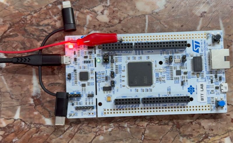
In part one of what is intended to be a series on developing an STM32-based oscilloscope, [BTTLab] demonstrates a how to use the built-in ADC of an STM32F207 MCU to develop a straightforward single-channel oscilloscope. This can be followed along both via the YouTube video and the GitHub repository for this single-channel version.
Of course, an MCU’s ADC generally won’t hold a candle to a dedicated ADC for oscilloscope purposes – along with the typical beefy FPGA-based processing – with even a basic Rigol DS1054Z hitting a cool 1 GSPS, but the 2 MSPS at 12-bit resolution achieved by an STM32F207 isn’t shabby either. For more basic, low-frequency circuit and protocol debugging it would already be enough.
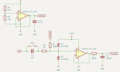
One thing briefly touched upon in the video is the front-end. The ADC’s inputs are rated for a specific voltage range, typically 0 to 3.3 V when running the MCU off 3.3 V, so you do not want to put higher or negative voltages into said ADC input. This is where measuring something like AC becomes rather tricky and you can get some exciting releases of magic smoke.
The demonstrated single-channel oscilloscope firmware uses the ST HAL, so it might be somewhat easy to target other STM32 MCUs as well, though naturally ADC performance will differ per MCU family and sometimes sub-family, so make sure to read the datasheet and programming manual before you dive in too deep.












Schottky protection is useless since the 3v3 LDO can’t sink current.
They should have used an active shunt circuit:
https://www.phippselectronics.com/adc-input-protection-circuit-using-transistor/
Why does that noise show up in end result?
Is that some DMA/uart glitch?
Should be good enough for a VI-tracer with STM32
Check ST RM0008. DMA can have quite a lot of jitter (depending on the code). This can affect ADC readings probably.
ORIGINAL STM32duino “Pig Scope”
http://github.com/pingumacpenguin/STM32-O-Scope/wiki
From the old forum, excerpts from the thread I started back in 2015 that created ahull’s version of the Pig-O-Scope, greatly enhanced by code fragments from madias and victor_pv.
Ancient perhaps, but there are a few genuine nuggets in how the group thinking collective evolve toward a final project.
http://sparklogic.ru/projects/10-o-scope-revisited.html
I thought it was a case of deja vu ;-)
Thanks Ray.
The specs looks like the typical junk kit found at amazon and aliexpress. A cheap microcontroller doing the job of proper hardware, resulting in sample rates sufficient for audio only, if you are lucky. Also note the lack of any kind of hardware trigger. And not accepting negative input voltages is ridiculous.
Input scaling and protection would indeed be the task of a proper voltage probe / frontend. However, even when considering it part of a DAQ system, it’s leaving so many things on the table, like data streaming via ethernet, timer trigger source configuration for interleaving to achieve 6 MSps, and probably an external reference.
I wouldn’t say no to a small current probe in glscopeclient that makes do with µC for interfacing, data handling and mixed-signal stuff, paired with e.g. a CT433 (well-matched 1 MHz BW TMR current sensor and too noisy for anything beyond 12-14 bit).
As someone who bought a real oscilloscope so I could check if the inverter in my ford maverick hybrid was pumping out a square wave or sine (sadly it was square) I kinda wish there were more cheapo ones out there; not all of us need the insane features all the “real” ones have… particularly when they’re all a borjillion dollars and you only have a singular use case.
Heard of FNIRSI?
heh i have to imagine there is, like you say, a proper market for the “junk kit found on amazon and aliexpress”. someone must buy one wanting it for what it is instead of being disappointed! but i think Tux2000’s point is that this project has been done already a zillion times, and generally to a higher quality.
fnirsi is garbage. partly because they outright lie in their specications, and on top of that they actrively try to hide the mailfunctioning hardware in their software, for example by heavy averaging.
Both Owon and Hantek make usable handheld scopes, with prices starting below EUR 100. I think I like the “zeewei” scope (in landscape format) It has two channels, dedicated buttons for timebase and voltage axis and a decent bandwidth.
Alientek DM40 may be interesting, but I’m not sure what it is exactly. The lowest cost version seems to be a (graphing) DMM, while the more expensive variants seem to have (some) oscilloscope aspirations.
On the low end there is also jyetech with the DSO138 (not so good) and DSO150 (DSO Shell). Both of these are also based on STM32F103 (maybe a chinese clone these days) I do sort of like my DSO 150 and use it more then I use my Siglent SDS1104X-E. The DSO Shell does not have a fan and it’s “good enough” to keep an eye on some PWM signals and such while I’m developing firmware. There are also alternative / open source variants of the software for this. For the EUR 30 these boards are also already attractive just as a generic development board with TFT, buttons and rotary encoder.
I could afford Rigol DS1052E easily as a university student. All it took was to wander suburbs in the evenings, proactively collecting scrap metal.
For something like that, an analog scope would work just fine. You can usually pick them up at ham radio swapmeets pretty cheap. Even an old synchronous sweep tube scope would be sufficient. Those can often be found for under $10, but they will need the capacitors replaced before you power them up.
As he probably looks at in later videos, the three 12bit ADC’s can be interleaved for a 6MHz sampling rate. That is technically enough for a bandwidth less than 3MHz, and an OK visual representation of 1MHz.
Ugh, the black gloves.
Reminds me, I once demonstrated equivalent-time sampling on an AVR-DA. This doesn’t do anything very impressive — time is quantized by peripheral clock of course, and the internal ADC’s analog bandwidth is rather modest (maybe 1 or 2MHz by my estimation; consistent with the manual’s description). Maybe I should make that into a proper project some time.