
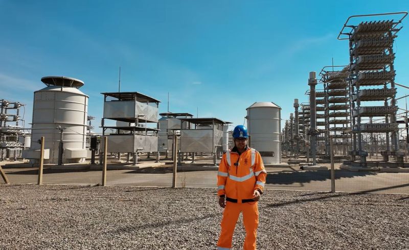
A fun way to think about a national electrical grid is as a massively upscaled electrical circuit, one in which you have multiple power supplies injecting AC power, with various bits and bobs involving resistors, inductors and capacitors in between working to synchronize and clean-up this power before it gets to the end users. Recently [Jordan Taylor], also known as [The Electric Brit] took a look at the grid’s harmonic filters that do a lot of this sinewave scrubbing after the HVDC to AC conversion.
Using a UK-based line-commutated converter (LCC) HVDC converter station as a physical example [Jordan] takes us through the elements of this harmonic filter, what it is, what it does and why it’s a necessity. The design considerations with components at this immense scale are also covered, along with the types of filters possible.
The Cliff’s Notes version is that following the conversion step from said HVDC there are harmonics introduced in the AC, not unlike in a much lower-voltage converter. This results in a noisy sinewave that can potentially cause harm to AC-powered devices, not to mention cause heating and other losses along the way. The answer is naturally to add an LC-filter, just on a slightly larger scale than for consumer electronics.
Also noted by [Jordan] is the nice synergy of these harmonic filters when it comes to absorbing and generating reactive power on the AC grid, due to their massive capacitors and inductors. This helps to dampen oscillations on the grid and thus further contributing to its stability.












I heard that sometimes two capacitors of different values provide competing DC isolation between the two inputs of a grid transformer. Then there is the issue of voltages phasing between the two inputs (do the math for two sinusoids in quadrature with differing phase and/or amplitude. Or just simulate it in Falstad app). The enormous reactance of the grid can help in this case. Legacy system had two capacitors implemented as one device (kinda like modern two input MOSFET), and an indicator for frequency difference (independent of phase difference). Modern grid is using PLC analog/digital DAQ units & displays. I would really like to see some detailed tear-downs, anyone has more?
I personally have nothing to add but that’s really cool
Near the start he describes power which doesn’t follow a clean sine wave as being bad for certain electronics, he then brings up the example of a computer power supply… pretty sure a power supply, an SMPS, is literally the type of thing most tolerant of dirty sine waves, it’s all those AC powered devices that aren’t behind an SMPS which need cleaner power?
Almost all (never seen one that did not) modern AC line powered switching supplies convert the line voltage to DC before switching it to drive the primary of a transformer. So the input AC doesn’t need to be a perfect sine wave.
Oops sorry for reporting your comment! Damn touchscreen
The majority of modern PC power supplies work fine with square wave inverters.
The necessity for a clean sine wave may have been required for computers of the 60’s and 70’s (even early 80’s) when linear supplies were all the rage.
Old TVs were the ‘electronics of highest susceptibility’ as harmonics in the power would show up as very visible lines/bands in the picture.
LCCs also usually run large banks of synchronous capacitors to correct the phase offset introduced by traditional SCR valves.
I know at this point we are one century too late to switch, but wouldn’t a DC grid be much easier to handle?
Since solar brought the whole grid management into the news, my mind simply cannot comprehend how complex the whole system behind the sockets is
Maybe a better transformer?
https://youtu.be/e_eEcPysMlQ
How would grid synchronisation work with DC? With AC, mismatches with supply and demand cause a frequency shift.
It seems that grid synchronization between load and generation would be reflected in the voltage. When connecting a generator one would need to ensure polarity and voltage is matched with the grid rather than matching frequency and phase.
My understanding is that A/C is a necessity for efficiency; when you send DC long distances, the magnetic field it creates dampens the current. A/C reverses fast enough to prevent a magnetic field from developing enough to interfere significantly.
its actually exactly opposite. AC has massive losses over logn distances because of the magnetic field. thats why very high voltages with as low as possible currents are used. in the past AC was easier to transform up and down. jsut 2 coils and thats it. but now we have efficeint DCDC switches (whcih did not exist in the past). so a DC grid could be more effiecient now.
In short – no. DC makes sense at low voltages and at very high voltages over long distance but for the huge bit in the middle AC is still more efficient for a multitude of reasons.
Going DC wouldn’t simplify it either because you can’t just hang the DC output from a solar farm onto the DC grid, so you’d still need all the conversion stuff anyway to match voltages, and at that point you may as well be making AC and using simple dumb transformers to do the heavy lifting of stepping up/down.
I wonder how many lineman die from generators, or the number of devices fried by dirty power.