
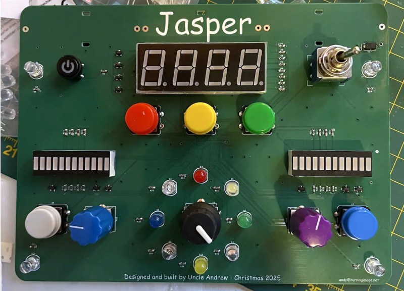
While you may not be familiar with the term “busy board”, you’ve almost certainly seen one. It’s the sort of toy with a bunch of buttons, switches, and of course LEDs, that are designed to keep young children entertained. As it so buttons, switches, buttons, and LEDs also keep hardware hackers entertained — doubly so if they are the ones designing said busy board in the first place.
That’s where we find [Andy], or should we say, [Uncle Andrew]. Last Christmas he decided to scratch build an electronic busy board for his nephew, and while it might not be a terribly complex piece of kit from a technical standpoint, it’s a fantastic multidisciplinary project in that it’s really equal parts hardware and software. While it would surely be possible to implement a gadget like this entirely in hardware, [Andy] took the modern hobbyist approach of offloading some of the task to a collection of carefully arranged ones and zeros.
In the write-up, [Andy] goes over the decisions he made while designing and building the device. This ranges from the extra effort put in to keep the PCB down to two layers and the logic behind LED multiplexing. This extends right into the software aspect of the project, with a surprisingly deep explanation of how the code uses timers and interrupts to run the show as efficiently as possible, maximizing the run time of the PIC18F67K40 microcontroller on a trio of AAA batteries.
It’s a fun read about a low-stakes project that’s made all the better by the personal touch. Just like the kids of makers and hardware hackers, [Andy]’s nephew is a lucky to have somebody like this in his life.











What an awesome project!
Makes me think fondly back to my first childhood kit last century. (Replaced my Mechanno)
I will never forget those childhood spring connectors.
It’s a microcontroller trainer!
When his nephew outgrows the default program, he can use it to learn to program.
I’d love to make one of these for my nephews and show him how it works, but they think I’m a lame jerk, and don’t communicate until it’s birthday, or Xmas. Or look up from their screens. Then I remember why I was interested at their age in such electronic goodies, because people suck. Merry F’n Halloween, losers.
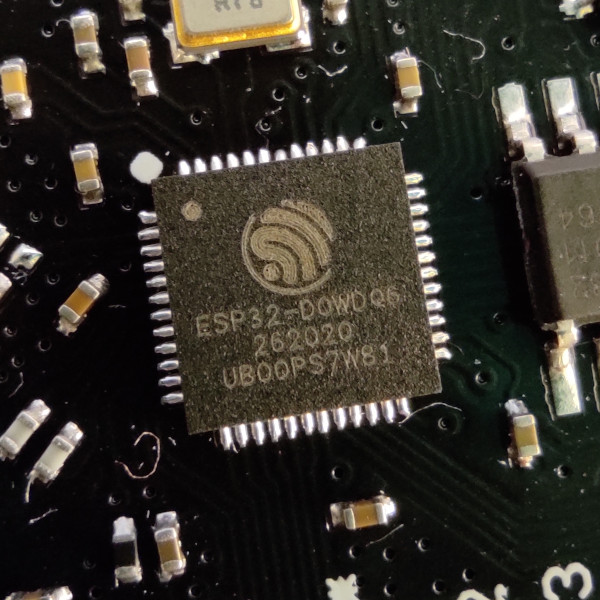
next step would be to connect it to a esp32 or teensy synth, and have it generate awesome sound based on the knobs and visualized bij the leds.
This! I have found almost the same thing as this as an existing product (even the knob with leds around it) and was planning on stuffing an esp32 in and have a cool doodle synth!
Huh, mutli-colour bar graphs, neat!
And purple coloured potentiometer knobs, I didn’t realise I need some of those!
Remember something like this appearing every once in awhile as a project in electronics hobbyist mags like Radio-Electronics or Elementary Electronics back in the day. One article called it a Digital Do-Nothing and that stuck with me till now. In addition to the bar graph, it offered LED decimal readouts in random, count-up and count-down. (Truthfully, I think I’ve glommed all the features ever offered into a Super DD-N in my fading memory banks 😶🌫️🫨🦠🧑🦯🧑🦽🧑🦼⛓️💥