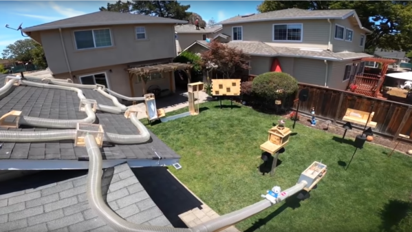
6 panel diagram of process

Add Conductive Traces On Vacuum Formed Plastic With 3D Printing

Surface conductors on vacuum formed parts appear in many hacks, from cosplay armor to 3D touch pads and smart objects. But making them has always been painful. Either they had to be hand painted after forming, which looked sloppy and was labor intensive, or they had to be printed with some difficult to use stretchable ink tech. [Freddie Hong] and his group have another solution, using tech most hackers already have – a 3D printer and a vacuum former.

plastic tray with electrodes to sense foil wrapped chocolates
Smart tray created by this method.

They 3D print the traces with conductive PLA filament directly onto a base plastic sheet, and then vacuum form the whole thing. The filament is happy to deform when heated – it’s printer filament.

We like this process.  We’ve found conductive filament isn’t reliably resistive across vertical layers, but is reliable in the XY plane. Their method only requires one layer. Also, they suggest 3D printing a layer of non conductive PLA atop most of the conductor, like a PCB solder mask.

Conductive filament has a fair bulk resistance. They suggest electroplating it before applying the top mask layer. They also are exploring 3D printing logos, stripes, and such with colored filament, or even making surface detail like rivets on model parts or adding thickness where the plastic thins during vacuum forming.

Designing the 3D print requires guessing what bit of plastic sheet ends up where in the vacuum formed final part.  His group used a commercial program, t-sim,  to do the prediction and Grasshopper to import the result into Rhino3D. This seems a lot for a home hacker. Drawing lines on a test sheet and vacuum forming seems simpler.

We’ve looked at vacuum forming before. We did a piece on 3D printing bucks , and covered [Ted Brull]’s Kevo vacuum former back in 2015.

Thanks to [howielowe] for the tip.

Blu-ray player with 3 slides on a disk

Blu-ray Microscope Uses Blood Cells As Lenses

When you think of high-throughput ptychographic cytometry (wait, you do think about high throughput ptychographic cytometry, right?) does it bring to mind something you can hack together from an old Blu-ray player, an Arduino, and, er, some blood? Apparently so for [Shaowei Jiang] and some of his buddies in this ACS Sensors Article.

For those of you who haven’t had a paper accepted by the American Chemical Society, we should probably clarify things a bit. Ptychography is a computational method of microscopic imaging, and cytometry has to do with measuring the characteristics of cells. Obviously.

This is definitely what science looks like.

Anyway, if you shoot a laser through a sample, it diffracts. If you then move the sample slightly, the diffraction pattern shifts. If you capture the diffraction pattern in each position with a CCD sensor, you can reconstruct the shape of the sample using breathtaking amounts of math.

One hitch – the CCD sensor needs a bunch of tiny lenses, and by tiny we mean six to eight microns. Red blood cells are just that size, and they’re lens shaped. So the researcher puts a drop of their own blood on the surface of the CCD and covers it with a bit of polyvinyl film, leaving a bit of CCD bloodless for reference. There’s an absolutely wild video of it in action here.

Don’t have a Blu-ray player handy? We’ve recently covered a promising attempt at building a homebrew scanning electron microscope which might be more your speed. It doesn’t even require any bodily fluids.

[Thanks jhart99]