Built-in batteries put a timebomb inside devices, with especially the calendar aging feature of Li-ion chemistries setting a hard limit on when you’ll have to toss the device or figure out a way to replace the battery somehow. Here the EU’s Battery Regulation policy with the 2027 implementation of the user-serviceable battery requirement provided a lot of hope. Now six new categories of exemptions are diminishing what could have been a bonanza of easy repairability.
Most notable here are smartwatches, fitness trackers, wireless earbuds and other so-called ‘wet devices’, which as GSMArena also notes is an area where having a user-replaceable battery might affect features like being water-resistant. Something which is also relevant for e.g. outdoor wireless speakers. There’s also a new exemption for smartphones, where if its battery retains at least 83% of its original capacity after 500 charge cycles, battery replacement has to be only replaceable by professionals. Which is probably code for ‘glue, hotplates and prying tools’.
Considering just how daft of an idea built-in batteries are, this is somewhat disappointing to see. While it’s understandable that ‘wet devices’ get such broad exemptions, it should be noted here that advanced technologies like gaskets are neither complicated nor expensive. You can even hand the average user a tube of RTV silicone and let them go to town on a part in the happy knowledge that there’s never such a thing as ‘too much’ RTV silicone.
It is likely that there was some pressure from the industry on the EU to not change too much, but at the very least us happy few in the EU will be getting a new Nintendo Switch 2 with easily replaced battery in both the main unit and its controllers. For the average rechargeable device you keep kicking around the house this should also still apply as long as its manufacturer cannot squeeze it into one of these exemption categories.
The Right to Repair battles shall continue.


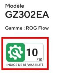 A few years ago, France introduced a mandatory repairability score for consumer goods like laptops and tablets. It involves five criteria that range from documentation and availability of spare parts to ease of disassembly, with the manufacturer using a government-provided checklist to determine their score.