Starlink’s Inter-Satellite Laser Links Are Setting New Record With 42 Million GB Per Day

Slide from the SpaceX Starlink presentation on mesh routing via the laser links. (Credit: PCMag/Michael Kan)

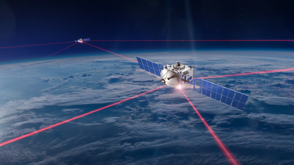
Although laser communication in space is far from novel, its wide-scale deployment as seen with SpaceX’s Starlink satellite internet constellation has brought the technology to the forefront like never before. This was quite apparent during the SPIE Photonics West event on January 30th when [Michael Kan] and other journalists attended a presentation by SpaceX’s [Travis Brashears] on the inter-satellite laser communication performance that was first enabled with the Starlink v1.5 satellites.

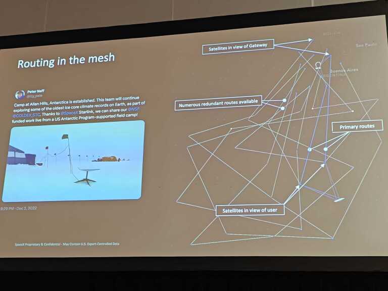
Among currently active inter-satellite communication systems, Starlink is by far the most numerous and with the highest bandwidth, reaching over 42 PB per day across its over 9000 space lasers (yes, that is over 9000) for a 5.6 Tbps throughput. Since these satellites form a mesh network with their 100 Gbps laser transceivers, a big part of using it efficiently is to route any data with the least amount of latency while taking into account link distance (maximum of 5,400 km), link duration (up to multiple weeks) and presence of other Starlink satellites before they become within reach. With this complex mesh in LEO, this also means that a very high uptime can be accomplished, with a claimed 99.99% due to rapid route changing.

For the future, SpaceX has plans to not only keep upgrading its own Starlink satellites with better laser transceivers, but to also make them available to third-party satellites, as well as beam the lasers directly down to Earth for ground-based transceivers. The latter is still cutting edge, despite it being tested to beam cat videos to Earth from Deep Space.

Decoding JS1YMG: First Ham Radio Station On The Moon After SLIM Mission

When Japan’s SLIM lunar lander made a rather unconventional touch-down on the lunar surface, it had already disgorged two small lunar excursion vehicles from its innards: LEV-1 and LEV-2. Of these, the LEV-1 is not only capable of direct to Earth transmission, but it also has been assigned its own amateur radio license: JS1YMG, which makes it the first Ham radio station on the Moon. LEV-1 receives data from LEV-2, which is transmitted to Earth using its 1 Watt UHF circular polarization antenna as Morse code at 437.410 MHz. Although the data format hasn’t been published, [Daniel Estévez] (EA4GPZ) has been sleuthing around to figure it out.

Using captures from the 25 meter radiotelescope at Dwingeloo in the Netherlands, [Daniel] set to work deciphering what he knew to be telemetry data following a CCSDS standard. After some mix-and-matching he found that the encoding matched PCM/PSK/PM with a symbol rate of 64 baud and 2048 kHz subcarrier. The residual carrier is modulated in amplitude with Morse code, but initially this Morse code made no sense.

Continue reading “Decoding JS1YMG: First Ham Radio Station On The Moon After SLIM Mission”

Sega’s AI Computer Embraces The Artificial Intelligence Revolution

Recently a little-known Sega computer system called the Sega AI Computer was discovered for sale in Japan, including a lot of the accompanying software. Although this may not really raise eyebrows, what’s interesting is that this was Sega’s 1986 attempt to cash in on Artificial Intelligence (AI) hype, with a home computer that could handle natural language. Based on the available software and documentation, it looked to be mostly targeted at younger children, with plans to launch it in the US later on, but ultimately it was quietly shelved by the end of the 1980s.

Part of the Sega AI Computer's mainboard, with the V20 MPU and ROMs.
Part of the Sega AI Computer’s mainboard, with the V20 MPU and ROMs.

The computer system itself is based around the NEC v20 8088-compatible MPU with 128 kB of RAM and a total of 512 kB of ROM, across multiple chips. The latter contains not only the character set, but also a speech table for the text to speech functionality and the Prolog-based operating system ROM. It is this Prolog-based environment which enables the ‘AI’ functionality. For example, the ‘diary’ application will ask the user a few questions about their day, and writes a grammatically correct diary entry for that day based on the responses.

On the system’s touch panel overlays can be used through cartridge or tape-based application to make it easy for children to interact with the system, or a full-sized keyboard can be used instead. All together, 14 tapes and 26 cartridges (‘my cards’) had their contents dumped, along with the contents of every single ROM in the system. The manual and any further documentation and advertising material that came with the system were scanned in, which you can peruse while you boot up your very own Sega AI Computer in MAME. Mind that the MAME system is still a work in progress, so bugs are to be expected. Even so, this is a rare glimpse at one of those aspirational systems that never made it out of the 1980s.

Fixing A Malfunctioning Keithley Model 179 Digital Multimeter

Inspired by electronics repair videos on YouTube, [Steven Leibson] recently found himself hunting down something to fix on eBay. This ‘something’ ended up being a  certified classic: a Keithley Model 179 digital multimeter from 1978. Listed as non-functional, the unit arrived at his door for less than $50. There weren’t any exciting pops or smoke when he powered it on, but the display seemed to be showing nothing but random nonsense.

The Keithley Model 179 multimeter has a convenient calibration sequence printed on its electrostatic shield cover and a deadly exposed ac line fuse in the upper left part of the photo. (Image credit: Steven Leibson)
The meter has a convenient calibration sequence printed on its electrostatic shield cover and a deadly exposed AC line fuse in the upper left part of the photo.

Ultimately reviving this little piece of history was quite simple, with the main issue turning out to be a dodgy inter-board connector between the main and display boards. After admiring an old repair attempt made on the component, he removed both the male and female connectors, replacing them with new ones.

This uncovered issues with the PCB, as the FR4 material and the traces on it had begun to delaminate, probably due to the old adhesive giving up due to age. With pretty low trace density this wasn’t anything that a bit of care couldn’t work around, fortunately.

Before finding this dodgy connector, [Steven] first tried to clean the front mechanical connectors, which took multiple sessions. This was followed up by oiling the mechanism. With the connector fixed and some cleaning, the meter’s display now read correctly. It still has some issues with starting up though, which [Steven] reckons are due to the old capacitors in the device.

Presumably some recapping will round off this fun device revival experience, but for the time being a Keithley Model 179 has been saved from e-waste, to inspire generations to come.

The Gyro Monorail: How To Make Trains Better With A Gyroscope

The gyroscopic system for gyro monorail trains that Brennan developed. (Credit: Primal Space)

Everyone who has ever handled a spinning gyroscope found themselves likely mesmerized by the way it absolutely maintains its orientation even when disturbed. Much of modern technology would be impossible without them, whether space telescopes or avionics. Yet during the early 20th century a much more radical idea was proposed for gyroscopes, one that would essentially have turned entire trains into gyroscopes. This was the concept of the Gyro Monorail, with Louis Brennan being among those who built a full-sized, working prototype in 1910, with its history and fate covered in detail by [Primal Space], along with an accompanying video.

At first glance it may seem rather daft to have an entire train balancing on a single rail track, using nothing but gyroscopic forces to keep the entire contraption level and balanced even when you feel the thing should just tip over. Yet the gyroscopic system that Brennan created and patented in 1903 turned out to function really well, and reliably kept the train on its single track. Key to this was the use of two gyroscopic wheels, each spinning in an opposite direction, with a pneumatic system linked to a gear system between the two wheels that used the gyroscope’s precession in corners to quickly establish a new balance.

Despite this success, investors were unconvinced, and regular trains were already firmly established, and the system would also require that each car had its own gyro system. Even so, the idea of the gyro monorail never truly died, as evidenced by the recently created German MonoCab-OWL project. This targets converting single-rail sections into dual-rail, bi-directional service with no infrastructure investment required.

Thanks to [Stephen Walters] for the tip.

Continue reading “The Gyro Monorail: How To Make Trains Better With A Gyroscope”

Overview of the Gwyscope SPM controller.

Low-Cost DSP For Scanning Probe Microscopy

A scanning probe microscope comes in a wide variety of flavors, they all produce a set of data points containing the measurements at each location. Usually these data points form a regular 2D grid, but it can be more beneficial to change the density of measurements at certain locations, or even the height, which creates a much more complex probing path and subsequent (XYZ) data set.

Yet this should not deter anyone, as [Miroslav Valtr] and colleagues demonstrate in a July 2023 article in Hardware X where they use a Red Pitaya SBC along with custom Eurocard-format PCBs to create a low-cost-ish (<1,500 USD) open hardware Digital Signal Processor (DSP) they call Gwyscope.

How the Gwyscope controller fits into an example of a scanning probe microscope setup. (Credit: Miroslav Valtr et al., 2023)

The Red Pitaya itself is used as a convenient hybrid FPGA-based module with on-board signal processing hardware, with its Xilinx Zynq ARM-FPGA chip providing both an FPGA section to implement the feedback loop module in Verilog, as well as the means to run a Linux instance with the C-based software that connects via Ethernet to a remote workstation. This communication is based around the GwyFile library, which is part of the Gwyddion project. The scanning paths are generated using libgwyscan (see this presentation for an introduction).

The resulting scan data is saved as an XYZ data file, which can be read with the Gwyddion visualization and analysis program. Although far from a quick & easy afternoon project for the casual hobbyist, it could be a boon for universities and laboratories.

Thanks to [Nicolae Irimia] for the tip.

How To Build Your Own 16-Bit System-on-Spreadsheet

Back in the hazy days of the  early home computers, many of us would rejoice at running our first BASIC applications, some of us even built our own 8-bit system from a handful of ICs and felt elated the moment the connected LEDs, screen or other output device would show signs of life. It is this kind of excitement that [Inkbox] has managed to bring to the bane of every office worker: spreadsheet programs like Excel. How, you may ask? Why, by implementing a completely functional 16-bit system with 16 general purpose registers, 128 kB of RAM and a 128×128 pixel color display, all inside an Excel spreadsheet, making it conceivably the world’s first System-on-Spreadsheet (SoS).

Perhaps the most tantalizing aspect of this approach is that it provides a very good visual way to indicate what is happening inside the system using color codes and clearly segregated and marked functional elements. Not only can it be programmed manually, but [Inkbox] also created an assembler for the CPU’s ISA – called Excel-ASM16 – all of which is available from the ExcelCPU GitHub project page. The ASM is assembled into a ROM.xlsx file that can then be run by the CPU.xlsx file by triggering the Read ROM button. After this you are confronted with the realization that although it all works, it’s also incredibly slow, at about 2-3 Hz.

Still, with all the elegance of an IMSAI 8080 front panel, we cannot help but give full points for this achievement. Plus it gives many of us something to do during those exceedingly dull meetings where only serious applications like office suites are allowed.

Continue reading “How To Build Your Own 16-Bit System-on-Spreadsheet”