Annoying Cicada Magnet Is Nonetheless Authentic

We’ve all heard of those chirper devices that randomly make annoying noises for no other reason than sending people insane. This project from [Kousuke Saito] brings altogether more art to this idea, while still being quite annoying indeed.

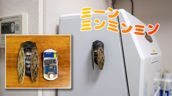
The build is essentially a replica cicada. [Saito] was inspired to build the device as the sounds of the insect remind him fondly of the summer. His design consists of a 3D-printed housing that roughly approximates something like a cicada, with two wings attached to a central body. In this case, the layer lines of the 3D print actually added to the realism of the ersatz insect The housing is nicely painted to serve as an adequate simulacra to those who aren’t up on their entomology.

Inside, there’s an ATTiny 85 paired with an MP3 playback module and a small speaker. It’s charged with reproducing the noise of various cicadas. It’s setup with an ingenious mechanism to switch it on. There are magnets installed in the base which allow it to stick to metallic objects. There’s also a switch in the bottom of the device. When it magnetically attaches to a surface, that switch is depressed, and the cicada starts playing, well… cicada noises. [Saito] notes that a patent has been secured for the idea.

We’ve seen other cicada-themed projects before, astoundingly. Video after the break.

Continue reading “Annoying Cicada Magnet Is Nonetheless Authentic”

Building A Truss-Braced Model Airplane: Sense Or Nonsense?

Following NASA’s recent results with truss-braced wing airplanes and the benefits this could bring to full-sized airplanes, [Think Flight] figured that if it helps with those airplanes, perhaps it may also be a boon for model airplanes. With the recent construction of a carrier airplane for smaller drones, he decided to give the concept a whirl to see whether it would make a difference compared to a regular wing design. This carrier airplane features a payload bay that can be opened in flight to release the drones stored inside it, making any potential increased payload capacity and improvements to the flight characteristics very welcome.

Continue reading “Building A Truss-Braced Model Airplane: Sense Or Nonsense?”

Calibrating Thermal Cameras With Hot Patterned Objects

Thermal cameras are great if you want to get an idea of what’s hot and what’s not. If you want to use a thermal camera for certain machine vision tasks, though, you generally need to do a geometric calibration to understand what the camera is seeing and correct for lens distortion. [Henry Zhang] has shared various methods of doing just that.

It’s all about generating a geometrically-regular thermal pattern.

To calibrate a thermal camera, first you need a thermal pattern. This is like typical test image for a camera or screen, but with temperatures instead of colors. [Henry] explains several methods for doing this. One involves using a grid of nichrome wires to create a thermal pattern for calibration purposes. Another uses discs of cold aluminium inserted into a foam board. Even a simple checkerboard can work, with the black spaces heating up more from ambient sunlight than their neighbouring white spots. [Henry] then explains the mathematical techniques used for calibrating based on these patterns.

It’s a useful primer on the topic if you’re working with thermal camera systems. We’ve looked at some other interesting machine vision topics before, too. If you’ve got any great thermal imaging tips of your own, don’t hesitate to drop us a line!


It’s A 486 Computer, On A Breadboard

Ever since the 1970s, a frequent project has been to take a microprocessor and construct a computer system on a breadboard or stripboard. Usually these machines feature a familiar 8-bit processor such as a 6502 or a Z80 because of their breadboard-friendly DIP packages, but there is surprisingly little reason why some of the more recent silicon can’t be treated in the same way. [FoxTech] is leading the way on this, by making a breadboard computer using an 80486DX.

A 1990-era 32-bit desktop CPU seems unpromising territory for this application, but its architecture is surprisingly accessible. It needs a breakout board to gain access to its various lines, but beyond that it can be interfaced to in a very similar way to those earlier chips.

So far there are two videos in the series, which we’ve placed below the break. The first one introduces the project and shows the basic set-up. A 486 running NOPs may produce a pretty light show, but as he starts to show in the second video, it’s capable of more. The eventual aim is to have a simple but fully functional breadboard computer, so he’s starting with logic to decode the 32-bit bus on the 486 into the 8-bit bus he’s going to use.

It’s fascinating to learn about how the 32-bit 486 handles its interfacing and deals with four bytes at once, and we’re very much looking forward to seeing this project play out. The 486 may be on life support here in 2023, but that doesn’t mean it can’t still receive some love.

Continue reading “It’s A 486 Computer, On A Breadboard”

Compact Mouse Jiggler Keeps Boss Off Your Back

The work-from-home revolution enabled many workers to break free from the shackles of the office. Some employers didn’t like the loss of perceived control though, and saddled workers with all kinds of odious spyware to monitor their computer activity. Often, this involves monitoring mouse movement to determine if workers are slacking off or not. Mouse jigglers aim to fool these systems, and the MAUS from [MAKERSUN99] is one you can build yourself.

The MAUS is not a mechanical system that moves a real-life mouse on your desk. Instead, it directly injects emulated mouse movements via USB. It runs on an ATtiny85, which is able to spit out USB HID commands with the help of the V-USB software USB implementation. Along with the microcontroller, MAUS also features a red LED and a WS2812B RGB LED for user feedback. It’s also available on Tindie if your boss has you so busy that you don’t have time to build one.

Mouse jigglers came to prominence as working from home became mainstream. However, they’ve been around for years.

Continue reading “Compact Mouse Jiggler Keeps Boss Off Your Back”

Study Hacker History, And Update It

Looking through past hacks is a great source of inspiration. This week, we saw [Russ Maschmeyer] re-visiting a classic hack by [Jonny Lee] that made use of a Wiimote’s IR camera to fake 3D, or at least provide a compelling parallax effect that’ll fool your brain, without any expensive custom hardware.

[Lee]’s original demo was stunning, and that alone is reason to revisit it. Using the Wiimote as the webcam was inspired back in 2007, because it meant that there was no hard computer vision work to be done in estimating the viewer’s position – the camera only sees IR LEDs anyway. The tradeoff is that you had to wear two IR LEDs on your head, calibrate it just right, and that only the person with the headset on gets the illusion just right.

This is why re-visiting the past can be fruitful. As [Russ] discovered, computing power is so plentiful these days that you could do face/eye position estimation with a normal webcam easier than you could source an old Wiimote. Indeed, he’s getting the positioning so accurate that he’s worried about to which eye he’s projecting the illusion. Clearly, it’s time for a revamp.

So here’s the formula: find a brilliant old hack, and notice if it was hampered by the state of technology back when it was done. Update this using modern conveniences, and voila! You might just find that you can take the idea further, simply because you have more tools in your toolbox. Nothing wrong with standing on the shoulders of giants.

But beware! Time isn’t sitting still for you either. As soon as you make your killer 3D vision hack, VR goggles will become cheap and ubiquitous. So get it done today, before your hack becomes inspiration for the future.

Meet The New Moteus BLDC Controller Board, The N1

[Josh] over at mjbots just released a new version of the moteus controller board, dubbed the moteus-n1. One change is that the volume and footprint size has been reduced. Considering many people, [Josh] included, use these controllers to operate robotic dogs, smaller is better. The previous moteus controller maxed out at 44 V, but the n1 can run at up to 54 V, allowing use of 48 V power supplies. And [Josh] improved the interface circuitry, making it much more flexible than before. This comes at an increased price, but he sells both versions — parts availability permitting. And like the previous versions of the moteus controller, this is an open source project and you’re free to build it yourself. You can check out the complete design package at the project’s GitHub repository.

One helpful point is that the firmware for the n1 is the same, it simply enables new features related to the I/O ports. This means a user could swap in a new controller with no impact to their system. Maintaining firmware compatibility was just one of the challenges [Josh] faced along the way. Squeezing additional functionality into the small number of user-exposed I/O pins was a chore, but dealing with supply chain issues was a big headache:

…make a revision that leveraged the parts I had, along with ensuring that the parts I needed were achievable to purchase in a reasonable time frame. Some parts orders for this batch were placed nearly a year ago.

Check out moteus if you need a brushless servo controller. We covered the previous major upgrade last year, which was primarily firmware and interface focused.