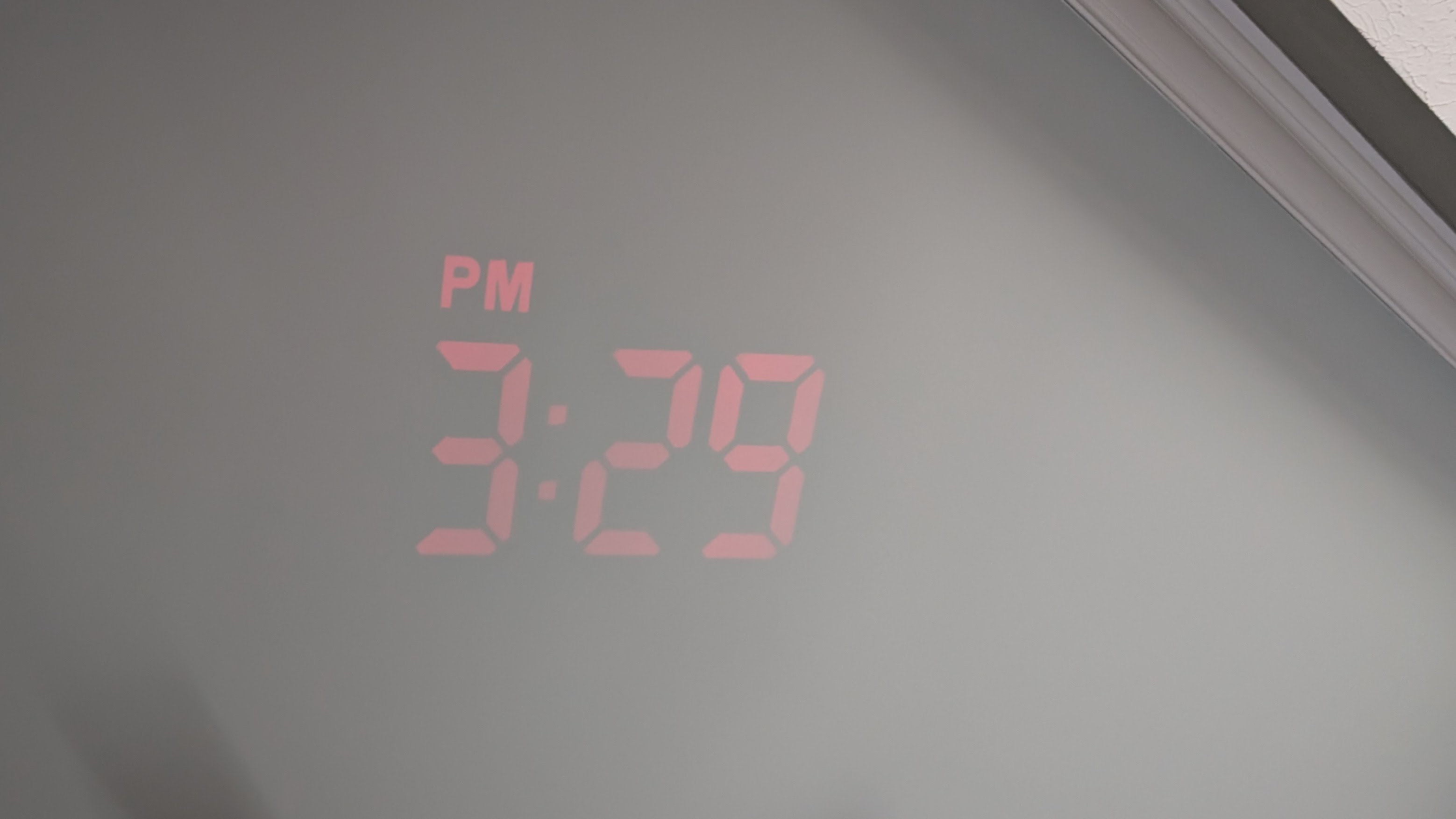
Math Breakthrough Helps Your Feng Shui

In 1966, a mathematician named [Leo Moser] proposed what sounds like a simple problem: What’s the largest shape you can move through a 1-meter corridor with a right-angle corner? Now, Korean mathematics whiz [Baek Jin-eon] claims to have solved the problem, nearly 60 years later.

The trick is, apparently, the shape of the sofa. By 1968, [John Hammerley] introduced a shape that did better than a rectangle, and by 1992, [Joseph Gerver] proposed something shaped like a phone handset, which remains the largest anyone had found, at 2.2195 square meters.

Continue reading “Math Breakthrough Helps Your Feng Shui”

Seeing Sound With A Laser

You can hear sound, of course, but what if you could see it with a laser? That’s what [Goosetopherson] thought about, and thus a new project that you can see in the video below was born.

The heart of the project is an I2S chip and an ESP32. Sound energy deforms a plastic film that causes a mirror to move. The moving mirror alters the course of the laser’s beam. Continue reading “Seeing Sound With A Laser”

DIY Grid Dip Meter Teardown

You don’t see them much anymore, but there was a time when any hobbyist who dealt with RF probably had a grid dip meter. The idea was to have an oscillator and measure the grid current as it coupled to external circuits. At resonance, the grid current would go down or dip, hence the name. In the hands of someone who knew how to use it, the meter could measure inductance, capacitance, tuned circuits, antennas, and more. [Thomas] takes a peek inside a homebrew unit from the 1950s in a recent video you can see below.

These meters often have a few things in common. They usually have a plug-in coil near the top and a big tuning capacitor. Of course, there’s also a meter. You have to pick the right coil for the frequency of interest, which both sets the oscillator frequency range and couples to the circuit under test.

Continue reading “DIY Grid Dip Meter Teardown”

Linux Fu: Yet Another Shell Script Trick

I’m going to go ahead and admit it: I really have too many tray icons. You know the ones. They sit on your taskbar, perhaps doing something in the background or, at least, giving you fingertip access to some service. You’d think that creating a custom tray icon would be hard, but on Linux, it can be surprisingly simple. Part of the reason is that the Freedesktop people created standards, so you don’t typically have to worry about how it works on KDE vs. GNOME or any of the other desktop environments. That’s a big win.

In fact, it is simple enough that you can even make your own tray icons with a lowly shell script. Well, of course, like most interesting shell scripts, you need some helper programs and, in this case, we’ll use YAD — which is “yet another dialog,” a derivative of Zenity. It’s a GTK program that may cause minor issues if you primarily use KDE, but they are nothing insurmountable.

The program is somewhat of a Swiss army knife. You can use it to make dialogs, file pickers, color selectors, printer dialogs, and even — in some versions — simple web browsers. We’ve seen plenty of tools to make pretty scripts, of course. However, the ability to quickly make good-looking taskbar icons is a big win compared to many other tools.

Docs

Depending on what you want to do, YAD will read things from a command line, a file, or standard input. There are dozens of options, and it is, honestly, fairly confusing. Luckily, [Ingemar Karlsson] wrote the Yad Guide, which is very digestible and full of examples.

Exactly what you need will depend on what you want to do. In my case, I want a tray icon that picks up the latest posts from my favorite website. You know. Hackaday?

Continue reading “Linux Fu: Yet Another Shell Script Trick”

Putting The M In A UNI-T MSO

[Kerry Wong] points out that the Uni-T MSO oscilloscopes have a logic analyzer built in — that’s the MSO, or Mixed Signal Oscilloscope, part — but you have to add the probes. He shows you how it works in a recent video below.

He’s looked at the scope’s analog capabilities before and was not unimpressed. The probes aren’t inexpensive, but they do unlock the mixed signal capabilities of the instrument.

Continue reading “Putting The M In A UNI-T MSO”

The Cutting Truth About Variable Capacitors

If you’ve seen a big air-variable capacitor, you may have noticed that some of the plates may have slots cut into them. Why? [Mr Carlson] has the answer in the video below. The short answer: you can bend the tabs formed by the slots to increase or decrease the capacitance by tiny amounts for the purpose of tuning.

For example, if you have a radio receiver with a dial, you can adjust the capacitor to make certain spots on the dial have an exact frequency. Obviously, you can only adjust in bands depending on how many slots are in the capacitor. Sometimes the adjustments aren’t setting the oscillator’s frequency. For example, the Delco radio he shows uses the capacitor to peak the tuning at the specified frequency.

You usually only find the slots on the end plates and, as you can see in the video, not all capacitors have the slots. Of course, bending the plates with or without slots will make things change. Just don’t bend enough to short to an adjacent plate or the fixed plates when the capacitor meshes.

Of course, not all variable capacitors have this same design. We’ve seen a lot of strange set ups.

Continue reading “The Cutting Truth About Variable Capacitors”

Trace Tracing To The Tunes

Some kind of continuity beeper has been a standard piece of gear since the dawn of electronics. Sure, you probably have an ohm meter, but sometimes you don’t care about the actual resistance. You just want to know whether something connects or doesn’t, especially with a PCB trace or a cable. But what if your beeper could tell you more? [Nick Cornford] asks and answers that question with a beeper that lets you estimate resistance via pitch.

The circuit is relatively simple. A short to ground causes a voltage divider to produce a fraction of the battery voltage and a FET to conduct that fractional voltage to a VCO via a high-gain amplifier. The VCO converts voltage to frequency, and an audio amplifier feeds it to the speakers.

The two amplifiers and the VCO require two dual op-amp chips. The original schematic sends the output to some relatively high-impedance headphones. To drive more practical ones, the circuit can drop one op amp and use another FET and a separate battery.

Of course, you have many design choices, especially for the audio amplification. There are plenty of VCO circuits, or you could probably substitute a small microcontroller with an A/D converter and PWM output. Yes, you can also make a VCO with a 555.

VCOs are common because they are at the heart of PLLs.