DIY Lathe DRO

Digital Caliper Sacrificed For DRO Project

In general, machining metal on a lathe or mill takes skill and patience as the accuracy of the cuts are important. To make those accurate cuts, it is important to know where the tool is located and how far it moves. For manual machines, the most basic method of determining position is by using graduated dials mounted on the hand cranks. Although these graduated dials can certainly be accurate, they may be difficult to see and they also require the operator to do math in their head on the fly with every full revolution of the dial. Another option would be a digital read out (DRO) which has an encoder mounted to the moving axes of the machine. This setup displays the exact position of the tool on an easy to read numeric display.

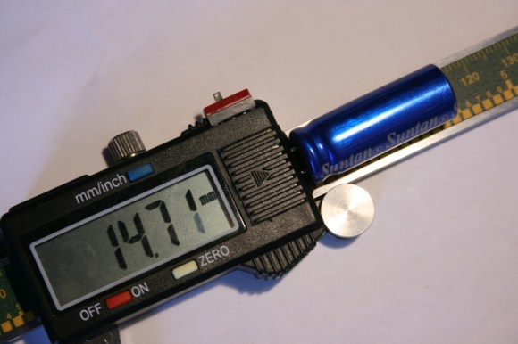
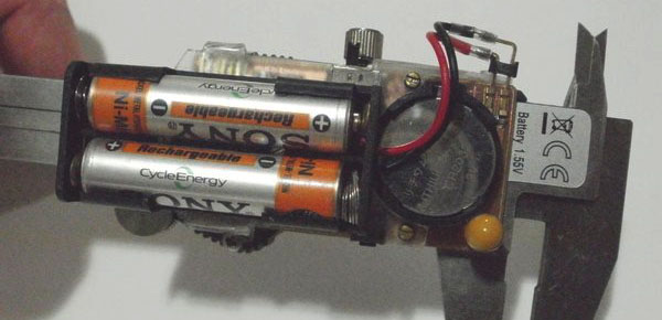
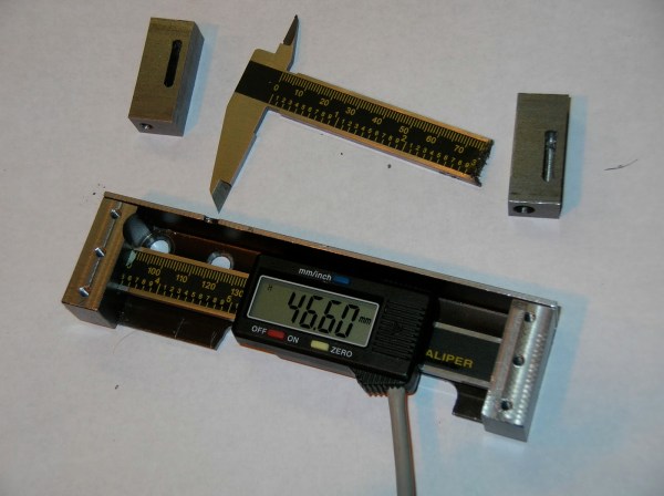
Professional DRO kits for mills and lathes can cost between a few hundred dollars to several thousand dollars.  [Robert] has a lathe, wanted a DRO but didn’t want to shell out serious cash to get it. He built his own for super cheap in an extremely resourceful way…. using a Harbor Freight Digital Caliper. A housing was first fabricated so that the added equipment would not hinder the axis travel of the lathe. The caliper was then cut to length, installed in the housing and the entire assembly was then mounted to the lathe.

DIY Lathe DRO
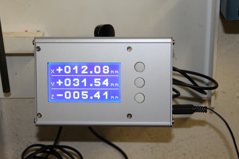
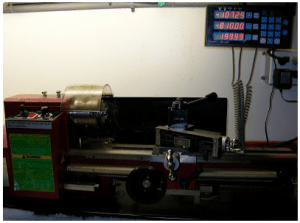
It is totally reasonable to use the stock caliper display to read the positional information, however, even these cheap digital calipers have connections for the encoder output data, which can easily be read by a microcontroller. That means it is super simple to hook these low-cost digital calipers up to a display remotely located in a more convenient position.


Three Axis Position Indicator With Digital Calipers

[Malte] just finished a little project for his Wabeco F1200 milling machine: a compact external display for three digital sliding calipers (Translated from German). As you may have already guessed, [Malte] was lucky enough to be able to fit disassembled calipers onto the machine and use them for positioning. Before embarking on this adventure, he noticed that there were similar projects present on the internet, but all of the calipers used had different data interfaces and protocols. The calipers that [Malte] bought have a mini USB connector, even though the interface itself isn’t USB. As he couldn’t find any information on that interface, he turned to his oscilloscope to decode the protocol.

[Malte] then built an AVR-based platform that reads out the three calipers and shows the position data on the dot matrix LCD shown above. The AVR firmware is written in a mixture of Basic and assembler language. The source code, schematics, and other resources can be downloaded from the project’s web page. We are impressed on the professional aspect of the final result.

Continue reading “Three Axis Position Indicator With Digital Calipers”

Supercharging Your Digital Calipers

supercapCalipers01

A dead battery in your digital calipers usually means a trip to the store for a new button cell. Not for [Trevor]. His hack substitutes a super capacitor, guaranteeing you’ll never need to rummage around for one of those pesky watch batteries again.

These calipers require only 20 seconds to reach a full charge that can last for a few days. Better still, [Trevor] designed a simple circuit with a voltage regulator at the end of the cord to allow charging via USB: just remember to flip the switch from “discharging” to “charging” mode. Although this is a fairly straightforward hack, its design is impressively tidy. The super capacitor fits perfectly at the end of the display and slides along with it, keeping it away from any important printed numbers. If these are the same calipers everyone seems to have these days, it looks like it may still fit in the provided case, too.

If you’re looking for more ways to beef up your calipers, try upgrading them with a Bluetooth module.

Giving Digital Calipers Bluetooth

[Fede]’s wife uses a pair of digital calipers to take measurements of fruits, leaves, and stems as part of her field research. Usually this means taking a measurement and writing it down in a log book. All things must be digitized, so [Fede] came up with a way to wirelessly log data off a pair of cheap Chinese calipers with a custom-made Bluetooth circuit.

Most of these cheap Chinese digital calipers already have a serial output, so [Fede] only needed to build a circuit to take the serial output and dump it in to an off-the-shelf Bluetooth module. He fabbed a custom circuit board for this, and after seeing the increased battery drain from the Bluetooth module, decided to add an external battery pack.

In addition to etching his own board for sending the serial output of the calipers to a Bluetooth module, [Fede] also put together a custom flex circuit to connect the two boards. It’s just a small bit of brass glued to a transparency sheet etched with ferric chloride, but the end result looks amazingly professional for something whipped up in a home lab.

Talking Digital Calipers Make Engineering More Accessible

talking-digital-calipers

The team over at NerdKits recently put together a device aimed to help make the process of measuring things more accessible to those with disabilities. [Terry Garrett] is a Mechanical Engineering student, and as anyone who is in the field knows, it’s a discipline which requires taking tons of measurements. Since [Terry] cannot see he was often asking classmates to assist in measuring items during labs, but when he got a job at a nearby design studio, he knew he would have to find a way to take those measurements on his own.

Enter NerdKits.

[Humberto] wrote in to share how he and his team built a set of talking digital calipers to assist [Terry] in his daily tasks. They based the design off a previous project they worked on, getting digital readout data from a set of calipers. The DRO information is fed into an ATmega382p, which pieces together pre-recorded sound bites to announce the size of the object being measured.

As you can see in the video below, the system looks to work very well, and [Terry] is quite pleased with his new talking tool. We love seeing these sorts of hacks, because they truly make a difference in people’s lives – excellent job!

Continue reading “Talking Digital Calipers Make Engineering More Accessible”

Hold, Fast, And Max Features On A Digital Caliper

While adding an RJ-11 connector to his digital calipers [BadWolf] slipped, shorting out a pin and accidentally discovered new features. He intended to add a port for reading measurement data electronically, but after the slip-up an ‘H’ appeared on the LCD screen and the measurement was frozen at the same number. At first it seemed like he may have killed the device, but this is actually a hold function. A little bit more playing around and he discovered that a combination of button presses can also enable a fast function which speeds up the rate at which the display changes its reading. There is even a max function that only updates the display if the reading is higher than any previously displayed measurement. These are nice features which he uses by connecting a momentary push switch between two of the output pins, details we gleaned from the annotated video after the break. He doesn’t say which pins work for him, but we’d bet one of them is the ground pin on the port, and the other is one of the two data pins. Do some investigating with your own calipers and let us know what you find in the comments.

Continue reading “Hold, Fast, And Max Features On A Digital Caliper”

Reading A Digital Caliper With A Microcontroller

[Maris] wanted a way to read measurements from a digital caliper electronically. He ended up using the TI Launchpad to accomplish this, but not all of the necessary hardware is seen above. The calipers cost him about $7 on eBay, and they have four interface pins which made this hack quite a bit easier. After a bit of probing he established their purpose; voltage, ground, clock and data. A bit of scoping proved that data was being sent in 24-bit burst in packets that are quite easy to decode.

From there it’s just a matter of interfacing with a microcontroller. The chip he’s using is an MSP430G2231 that runs at 3.3V, but the caliper’s logic high is only 1.5v. By constructing an adapter using a pair of transistors, the data and clock from the calipers are able to pull pins on the MSP430 low. This is collected and analyzed by [Maris’] firmware and can be read on a PC using a terminal program.

[Thanks Chris]