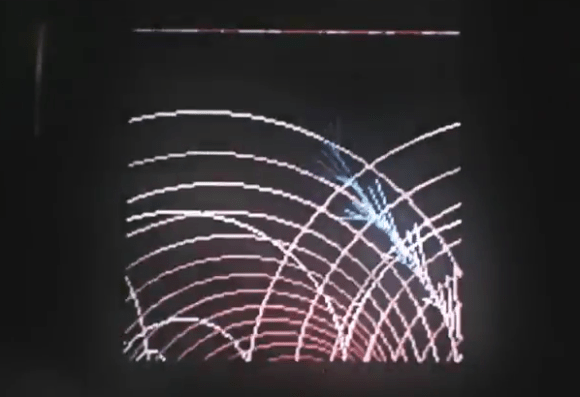
Siri Controlled Arduino Using Ruby

siri-proxy-ruby-arduino

This snippet of Hello World code lets [Nico Ritschel] turn the Pin 13 LED on his Arduino on and off using Siri, the voice-activated helper built into iPhones. The trick here is using the Ruby programming language to get Siri Proxy talking to Arduino via the USB connection. He calls the project siriproxy-arduino.

On one end of the hack resides SiriProxy, a package not approved by Apple which is capable of intercepting the Siri messages headed for Apple’s own servers. The messages are still relayed, but a copy of each is available for [Nico’s] own uses. On the other side of things he’s building on the work of [Austinbv’s] dino gem; a Ruby package that facilitates control of the Arduino. It includes a sketch that is uploaded to the Arduino board, opening up a Ruby API. The collection of code seen above defines the pin with the LED connected and then listens for a specific Siri commands to actuate it.

Take a look at [Nico’s] explanation of the module in the video after the break.

Continue reading “Siri Controlled Arduino Using Ruby”

Getting An Arduino To Control A Wireless Outlet

[Reza’s] methodical investigation of this remote controlled outlet let him patch in with an Arduino using a 433 MHz transmitter. This is a single-device unit, but the techniques used here should allow you to take control of wireless rigs that have multiple modules to control many devices.

We’ve seen some folks at our local hackerspace try to patch into the remote control itself. That used some type of weird button scanning (not just connecting a pin to ground or voltage) and didn’t pan out. [Reza] doesn’t even crack open the case of either of the units seen above. Instead, he goes straight for a wireless receiver he had on hand, using a logic analyzer to capture the signals coming from the remote.

Once he had a good snapshot of the signals sent when pressing the on or off button of the remote he set out to replicate it in his Arduino code. His function called setStateWithDelay takes three parameters: the transmit pin, the level (high or low), and a number of milliseconds to delay. Each signal calls this function many times, but working the bugs out is pretty easy; just capture the signal with the logic sniffer and compare to the stock remote.

7x7x7 LED Cube Driven By Arduino Mega

Sure, the physical build itself looks great, but it’s what [Michael] did with the firmware that impresses us the most. He’s using an Arduino Mega to drive the 7x7x7 cube and manages to squeeze out what he calls 142 frames per second with the setup. We’re not sure FPS is the right measurement, as we believe it’s the multiplexing rate that he’s trying to describle. It takes 144 uS to scan the entire matrix once. He performs the scan seven times per frame and the result is a flicker-free appearance, even to cameras.

You can see a video demonstration after the break. Since [Michael] emailed us directly with more details about the build we’ve pasted those below the fold as well.

If you’re looking for a more entry-level Arduino LED cube this 4x4x4 project is just the thing.

Continue reading “7x7x7 LED Cube Driven By Arduino Mega”

Stocker Monitors The Markets

stocker-monitors-the-market

If you can’t help but spend the day checking in on your stock prices this ambient device can help you cope. It monitors how the trading is going and illuminates an LED as feedback. Here the Apple stock is trading up so the light is green. The video after the break shows other stocks trading down, causing it to switch to red.

An Arduino interfaces with the custom application via USB. For now it looks like the two colors are all it’s capable of but we think there’s a lot more potential. Some creative coding could use factors like how much the stock has moved, trading volume, volatility, or a plethora of other data to give feedback. We could see a spectrum of colors (like on a temperature map) used to improve the level of feedback. And if the market really tanks there’s always the ability to add flashing!

The diffuser for the project is quite interesting to us. [Ali Reza Kohani] made it from a leftover scrap of acrylic. The bubbled surface was created with a heat gun before bending the sheet into an arc.

Continue reading “Stocker Monitors The Markets”

Gaming System Inside An Atari Joystick

gaming-system-inside-an-atari-controller

This original Atari controller is pretty small (take a look at that RCA cable for a sense of scale). Despite it’s size, [Kyle Brinkerhoff] managed to fit a complete gaming system inside the controller. This Pocket Sized Atari is a follow-up to another project he did called ArduPong which let him play Pong using a joystick and an Arduino. This rendition takes the external project box from that build and moves everything into one tight little package.

In the video after the break [Kyle] gives us a tour of the internals. The Arduino board he went with is an Ardweeny which is no bigger than the ATmega328 footprint so it can be easily mounted off to one side. The joystick internals have been replaced with the analog stick module from a PlayStation controller. That is where the button came from as well. Just connect this to a 9V battery and the composite video input of a TV and you’re ready to do some gaming!

Now if you just want that retro look for your Xbox Live games check out this Xbox 360 controller in an Atari joystick.

Continue reading “Gaming System Inside An Atari Joystick”

Humble Beginnings Of A Home Automation Project

humble-beginnings-to-a-home-automation-project

This board is the start of [Steven Pearson’s] quest to automate his home. The module will be used to prototype the rest of the project. Right now it uses an ATmega328 chip running the Arduino bootloader. This connects to one mechanical relay which we would wager is mains rated. The module will be controlled wirelessly via the wireless module seen in the foreground. That is a nRF24L01 board which he chose because of it’s bargain basement price tag of around $1.50.

There is much room for expansion in the system. You can see that a light-dependent resistor has been added to some of the microcontroller’s breakout pins. We would guess that [Steven] will use the hardware to develop for many different functions and will design more task-specific modules as the project progresses.

If you’re a fan of PCB milling and population you won’t want to miss the video after the break. [Steve] posted a fast-motion video of the entire process.

Continue reading “Humble Beginnings Of A Home Automation Project”

Prototyping A Low-resolution Handheld Gaming Rig

low-res-arduino-gaming

[Jason] has been hard at work on this Arduino-based low-res gaming platform. He even had a fab house deliver circuit boards to pull everything together. It’s a little small in his hands, and the graphics are limited to the 8×8 pixels provided by the display. But it still looks like a lot of fun and the code was written to make adding new games quite painless.

The board hosts an ATmega328 which drives the bi-color LED display using a pair of TPIC6B595 shift registers. Control is provided by a collection of buttons to either side of the display. The unit is powered by three AAA batteries held in a pack soldered to the back side of the PCB.

The image above shows [Jason] giving a Space Invaders game a try. The clip after the break shows respectable action, sound from a piezo buzzer, and it even scrolls your score at the end of the game. But you’re not limited to just one title. Adding new games is as easy as implementing a class in a new header file. You can get a feel for how this is set up by viewing the source code repo.

This reminds us of the Pixel Bros low-res system.

Continue reading “Prototyping A Low-resolution Handheld Gaming Rig”