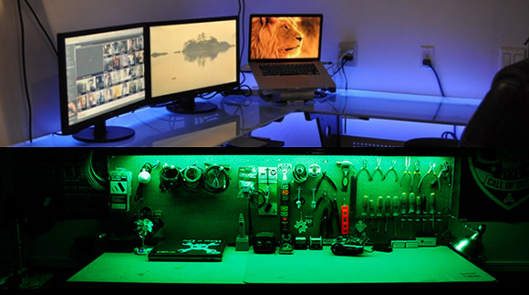
Papercraft Dial Is The Slide-ruler Of Current Limiting Resistors

led_resistor_dial_39

This paper dial makes selecting current limiting resistors a snap. [Giorgos Lazaridis] came up with the tool, which he describes in detail in the Worklog tab of his writeup. If you want one of your own he also posted a PDF which you can print, cut, and tack together.

At this point we can calculate resistor values for LED circuits without looking at reference material. But it wasn’t always like that. This wheel will be a fantastic tool for those just starting out in hobby electronics who are trying to grasp the theory behind lighting up a simple project. The outer wheel references the source voltage, with the inner being a gauge of forward voltage across the LED(s). Line those two values up and you can read the optimal resistor value in the window seen to the right. But wait, there’s more! As you can see in the video after the break the opposite face of the dial also includes a window which will tell you the power dissipation so that you may choose a properly rated resistor. Slick!

Continue reading “Papercraft Dial Is The Slide-ruler Of Current Limiting Resistors”

Replacement Drivers For Old LED Signs

led-sign-driver-replacement

The LED signs sitting idle on the left are brought to life by an Arduino replacement driver shown to the right. The big one is made by Signature Electronic and used as an advertising display like you would see in front of a business. [Bob Davis] picked it up on eBay being sold as non-working. After some power supply repair he set to the task of driving them with his own hardware.

The images he shared give us a good look at the parts used on the sign. The display area is made up of a set of eight 8×5 pixel LED modules. Each module has a key and slot in the top and bottom to help align the rows properly when building a larger array. They use TPIC6B595 shift registers (the same ones seen in yesterday’s low-res gaming hack) and 74HCT138 decoders to multiplex the pixels. Most of this info is shared in the second part of his post.

He hasn’t quite gotten the larger sign to run properly. Each row displays the same data but one pixel lower than the last. If you’ve got some insight on why this is happening we’re sure he’d like to hear about it.

[via Dangerous Prototypes]

8×8 LED Matrix Pendant Sealed In A Block Of Epoxy

8x8-led-pendant

This is the back side of [Dmitry Grinberg’s] 8×8 LED matrix pendant. He had seen the other projects that used a 5×7 grid but wasn’t really satisfied with the figures that can be drawn in that confined area when each pixel has only the option of being on or off. His offering increases the drawing area and includes the ability to display each pixel at several different levels.

He’s using an ATmega328 microcontroller soldered directly to the pins on the back of the LED module. He mapped out the IO in his firmware to make the soldering as easy as possible. To protect the hardware he fashioned a mold around the edges of the LED package using duct tape. The tape held epoxy in place as it hardened, encasing the microcontroller and holding the power wires and ICSP header tightly.

After the break you can see about six seconds of the device in action. The four levels of brightness for each pixel really do make quite a difference!

Continue reading “8×8 LED Matrix Pendant Sealed In A Block Of Epoxy”

Another Take On The Rear-window LED Marquee

re-window-led-display

This rear-window LED marquee will help let the driver behind you know when you’re planing to change lanes or make a turn. But it also includes the ability to send a message like “Back Off!”. [Robert Dunn] was inspired to undertake the project after seeing the one we featured back in October. We’d say his has a better chance of being street legal since it uses all red LEDs.

The marquee is a matrix of 480 LEDs, all hand soldered to form the nearly transparent 48×10 grid shown above. This is important to preserve visibility out the back window of his truck. It makes us wonder about the feasibility of using SMD instead of through hole components. That would certainly make it even less visible when not illuminated, but the assembly process would be much more difficult. That’s because the 5mm LED packages fit nicely in the grid of holes he drilled in some plywood which served as the jig during soldering. The presence of leads also made the soldering process manageable.

Power to an Arduino board is provided from the cigarette lighter adapter. A set of six shift registers drive the columns while the rows are controlled by a 4017 decade counter and some transistors. Check out the blinker test video after the break to get a look at what this can do while on the road.

Continue reading “Another Take On The Rear-window LED Marquee”

Glass Delay Line Slide Used In An RGB Lamp

glass-delay-lines-lamp

The spire used in this lamp is a part from an old television. It’s a glass delay line slide which pipes the light up from the Bluetooth controlled RGB lamp (translated) in the base.

We have looked at delay lines previously when [Dave Jones] tore down a camcorder to get at one. But we must have missed the EEVblog follow-up episode which explains how the glass slides work. The device uses physical distance to form a delay. Waves directed into the edge of the glass slide bounce around at an angle before being sensed at the collection point. [Lukas] liked the visual appearance of the part and decided to use it to add visual interest to his lamp project. The nature of the glass makes it perfect for directing the light up and away from the PCB.

The lamp consists of one RGB LED module controlled by an ATtiny2313 microcontroller. Also on board is a HC-05 Bluetooth module. This along with an app he wrote lets the user change lamp color and behavior wirelessly. You can see the lamp in action in the video after the break, but we think the camera shot probably doesn’t do it the justice it deserves.

Continue reading “Glass Delay Line Slide Used In An RGB Lamp”

A Blinky Fedora To Ring In The New Year

[Garrett Mace] decided to dress festive for New Year’s Eve. What he came up with is a fedora ringed in LEDs that react to music. The hardware uses 5050 LEDs on strips. Three of them encircle the head-gear providing a total of 114 RGB pixels. Each is a WS2811 module — a part which we’re seeing more and more of lately.

The video clip after the break starts off with a few minutes of demonstration. [Garrett] managed to code all kinds of animations for the hardware including several different styles of color sweeps and fades. You may start to think that the three bands always display the same patterns but keep watching and you’ll see a sparkle pattern that proves each dot can be addressed individually.

About 2:20 seconds into the video [Garrett] explains how he pulled it off and shows off the driver hardware. The strips are glued to a band of webbing that slides over the hat. The wires that drive the lights were fed through the center of some paracord and connect to an Arduino housed in a 3D printed case. Power is provided by a portable USB battery with a ShiftBrite shield and an MSGEQ7 chip complete the parts list.

Continue reading “A Blinky Fedora To Ring In The New Year”

Tie Tack Sends Morse Code Seasons Greetings

morse-code-tie-tack

For [Davide Gironi] made a holiday tie tack this year. It’s not made to look like Santa Claus, Frosty, or a Christmas tree. He simply wishes you a Merry Christmas (‘Buon Natale’ in Italian) by flashing the message in Morse code.

Two LEDs have been added to a plain tie tack. It is tethered to the logic circuitry that provides power and drives the red and blue lights accordingly. As you can see in the video after the break, red signifies the end of a letter, and long or short blue flashes correspond to dashes or dots. This doesn’t require much horsepower so he’s gone with an 8-pin ATtiny13 microcontroller (you might be able to find one of these in a light bulb if you look hard enough). The rest of the equipment includes a few resistors, a push button, and a coin cell for power. [Davide] uses a byte-packing technique he learned from a different project to store each letter as an 8-bit packet which means there’s plenty of room to store your message in the chip’s memory.

Continue reading “Tie Tack Sends Morse Code Seasons Greetings”