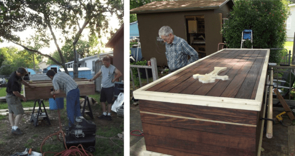
The BatBox: Portable Power, Polished And Professional. Plus Smoke!

batBox

About the size of a shoebox and stuffed with a compact battery/inverter combo, the BatBox packs a mean wallop at 480Wh. What else was [Bill Porter] supposed to do with his free time? He’s already mailed out electronic wedding invitations and built custom LED centerpieces for the reception. He and his wife [Mara] then made an appearance in a Sunday roundup tying the knot by soldering a circuit together. Surely the LED Tetris Tie would have been in the ceremony had it existed. This time, though, [Bill’s] scrounged up some leftover electronics to put a realistic spin on a Minecraft favorite: the BatBox.

A pair of 18V high energy density batteries connect up to a 12V regulator, stepping them down to drive a 110VAC inverter. The BatBox also supplies 5V USB and 12VDC output for portable devices. Unfortunately, [Bill]’s first inverter turned out to be a low-quality, voltage-spiking traitor; it managed to let the smoke out of his fish tank’s LED bar by roasting the power supply. Undeterred, [Bill] pressed on with a new, higher-quality inverter that sits on an acrylic shelf above the batteries. OpenBeam aluminum extrusion seals up the remainder of the enclosure, completing the BatBox with a frame that looks both appealing and durable.

The Cramp: A MSP430-powered Crane Lamp

theCramp

If you think your last project required a lot of soldering, take a look at [Multivac’s] remote controlled and fully-articulable desktop crane lamp. Sure, it’s a 430 microcontroller combined with an LED driver, 32 LEDs, PWM control, and some moving parts: but take a closer look at the structure. The Cramp uses an old HDD as its base, with the crane spinning around the main bearing that previously supported the platter. A system of spools and pulleys provides a reasonable range of motion to the rest of the build. Relocating the entire assembly, however, is evidently an unpleasant task.

[Multivac] based his design on a Liebherr LR1750 Crawler Crane, which he meticulously pieced together using leftover copper salvaged from an upgrade to his home’s mains wiring. A mountain of solder secures what must include several hundred joints—possibly more. The head of the lamp is an elegant exoskeleton-interpretation of industrial designer Eero Saarinen’s TWA Flight Center. You can see the Cramp in action in the video below.

Continue reading “The Cramp: A MSP430-powered Crane Lamp”

OSH Park Adds Board Sharing Feature

osh-park-board-sharing

OSH Park continues to get better and better. We think the recent addition of Project Sharing is a huge feature! Obviously this lets you order up the open source goodness posted by others with a minimum amount of effort. But to us there are a couple of other things that make this valuable.

First off, the ability to browse through the projects can be a huge inspiration for your own work. Secondly, the board files themselves are available for download, and it looks like you can post links to your repository if you so choose when sharing your project. This makes OSH Park something of a Thingiverse for PCBs. Browse through what’s offered then download the files to etch yourself or just to use as reference to see how others do things when laying out the traces. And of course the rock bottom prices offered make this a no-brainer for shared breakout board designs.

The Twitter post calls this the “early stages” of the feature. We can’t wait to see what they come up with as it matures.

Breakout Board For $11 LCD Module With Small Pitch

breakout-for-strange-pitch-LCD-screen

[Ibrahim] picked this little LCD module out because of its price point and resolution. In single units you can grab one of the 128×32 pixel displays for just $11. The only problem is that the pinout is too small to use with a breadboard. He whipped up a breakout board for it that throws in some extras.

First off, we like it that the board doesn’t add much to the part’s outline. What it does add is a Low-DropOut voltage regulator and a level converter. The upper range of the LCD’s input voltage is 3.3V, and these added parts make it possible to drive the device using 5V hardware like the Arduino Uno pictured above. While he was adding in parts he included a MOSFET to switch the backlight. This way he can use PWM for dimming as well.

We usually hit eBay when looking for LCD screens. A search for the NHD-C12832 part number didn’t turn it up. We tried out FindChips for the first time (owned by Supply Frame who just bought Hackaday) and it works just as well as Octopart which we’re more familiar with since we’ve seen some hacking of that site before.

Update: Home Security Monitoring Prototype

home-security-monitoring-prototype-update-1

This project is about home security monitoring, but the update is crack for electronics designers. [Simon Ludborzs] continues to work on his prototype and he’s fantastic about sharing his success and failure in a conversational manner.

In April we saw his initial design which combined a SIM900 GSM modem with his own board to let him monitor his home security system without hiring a monthly service. Above you can see a snap of his latest prototype. It’s not fully populated as he’s testing the power supply… which in this state puts out 0V. Obviously that’s not up to his design specification so he started hunting around for the issue. He tells a tale of woe which is near to our hearts. He removed Q6, which is BC807 transistor, in order to test the FET used on the board. This brought it to life and had him looking into the datasheet of the part and its footprint in Altium. The footprint is right, the schematic symbol is wrong. There’s a lucky fix though. Above you can see the original design. The fix was just to rotate the part. This is illustrated as a change in the layout, but it worked with the original pad location. They’re not square to the transistor’s legs but they do still fit the outline.

He goes on to stress test the PSU output and then discuss whether it’s enough for the rest of the project. All in all a fascinating read!

Polishing Optics Milled From Acrylic

acrylic-optics-finish-testing

[Ben Krasnow] milled some lenses out of cast acrylic and needed a way to get an optical finish on the tool-marked surface. He tested several acrylic finishing methods to achieve a crystal clear finish. The tests were done using flat chunks. A regiment of sandpaper, from coarse to fine, was used as the first stage of the operation. From there [Ben] sought out the best finishing step, starting with hand polishing tests, flame polishing, and methylene chloride vapor polishing (which is something along the lines of acetone vapor polishing for 3D printed ABS parts).

Flame polishing and vapor polishing are not really exact sciences… at least in the tests he performed. It was difficult to know exactly how long to expose the acrylic. Too short or too long resulted in poor clarity. Watch his video to get a look at all results. We’d say the the easiest way to make milled acrylic clear without achieving an optical finish is to flame polish it as it doesn’t really require that you sand it ahead of time. But [Ben’s] tests prove that you can’t beat hand polishing with 600 then 2000 grit sandpaper before finishing up with a liquid plastic polish.

Continue reading “Polishing Optics Milled From Acrylic”

Reverse Engineer A PSU To Change Its Output Voltage

reverse-engineering-psu

[Semicolo] has a bunch of old PSUs on hand which he pulled out of some Lexmark dot matrix printers. In their stock form they put out 40V, which is close to the 35V max he needs to run the stepper motors on a 3D printer he’s been building. So he reverse engineered the PSU to change its output.

On the left you can see the top of the PCB. [Semicolo] flipped it over and snapped a picture of the traces on the bottom of the board. With a bit of work in The Gimp (FOSS image editing software) he was able to convert the traces to black and white. Overlaying the picture of the top with a 50% transparency of the traces made it rather easy see the connections and generate a schematic for the hardware. That’s a really cool trick!

Figuring out how it’s supposed to work is a big step in achieving his goal. The next step was to see if he could bend the circuit to his will. He had previously run across ATX PSU hacks which changed the reference voltage in order to alter the output. He grabbed a datasheet for the HA17431 variable shunt regulator. It lays out how to tune the output based on values of a few external components. He dropped in one resistor and the output measured 31V, well within his target range.