How Not To Dim EL Panels, TRIACs!

We’ve all been there: an exciting brilliant idea, scratched onto a napkin, hastily plugged into a breadboard, all for naught.  Even the best ideas sometimes suffer from a heavy dose of reality.  [Ch00f] over at ch00ftech recently had a similar experience dimming an EL panel of his using a TRIAC and some clever waveform manipulation. Instead of tossing the parts across the room in a fit aside and moving on he goes into a detailed analysis of what went wrong.

This method differs from the way most EL drivers dim output loads, instead of chopping the output like a PWM controlled LED the TRIAC snips the ends of the waveform and makes an ugly but less powerful output. The issue with this method is that when you cut the waveform during non-zero crossings it causes massive current spikes. These can wreak havoc on a cheap EL inverter and generally cause headaches all around.  [Ch00f ] speculates that his woes may be due to the fact that EL wire is a capacitive load, causing voltage to fall out of phase with the current. This is one of those engineering problems with a thousand and one answers, we can’t wait to see what he comes up with.

Check out the writeup for all the “deets” (as [ch00f] would say) as it is a pretty good primer on TRIAC operation. If there isn’t enough glowy wire in this post you can also check out this sound reactive panel or an informative guide on EL or even more from [ch00f] in general.

Swapping Out Eee PC BGA Chip For 1.6 GHz Upgrade

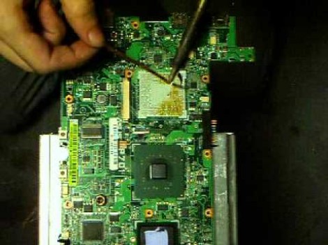
Personally we find this Ball-Grid Array chip-swap rather horrifying. But if you want to beef up the processor on your 701 Eee PC this is what you’ll need to go through. Not only did [Red Fathom] upgrade to a 1.6 GHz chip, but he managed to get the computer to boot up with the new hardware in place.

BGAs are notoriously hard to solder. This hack pulls it off using just a hot air gun. [Red Fathom] heats the board from the underside until the solder melts and he can pluck off the old chip. He then uses a solder braid and iron to remove extra solder from the footprint. After a little cleanup with a cotton swab and some flux he plops in an Intel Pentium M LV 778. It doesn’t look like he added any solder after the cleaning process. Perhaps he’s relying on the small amount left on the tinned pads of the board?

After the break you can see the soldering process and a video of the new processor booting Xandros.

Continue reading “Swapping Out Eee PC BGA Chip For 1.6 GHz Upgrade”

NAS-based Transcoding Facilitates Security Cam Viewing On IPhone

[Zitt] has a security camera which will send him messages any time it detects motion. However annoying this might seem, we’re sure he has his reasons for needing this much immediate feedback. The real problem comes when he goes to view the feed on his iPhone. His solution is to turn the camera’s notifications off, and use his own script to transcode a clip and shoot off an email.

As you can see above, the end result is a concise email that includes the recently captured clip, as well as links to the live feed. He has been storing the clips on an LG N4B2 Network Storage Server (NAS) and since he’s got root access to the Linux system on the device it was an easy starting point for the new system. After he compiled FFmpeg from source (which handles the transcoding) he started work on the script which backs up the recordings and sends the email messages.

One thing he wants to add is a method to clear out the old backup videos. Having encountered a similar issue ourselves we decided to share our one-liner which solves the problem. Find it after the break.

Continue reading “NAS-based Transcoding Facilitates Security Cam Viewing On IPhone”

‘Vortex-drive’ For Underwater ROV Propulsion

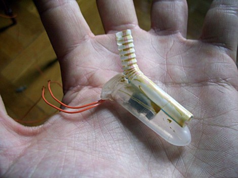
This is [Lee von Kraus’] new experimental propulsion system for an underwater ROV. He developed the concept when considering how one might adapt the Bristlebot, which uses vibration to shimmy across a solid surface, for use under water.

As with its dry-land relative, this technique uses a tiny pager motor. The device is designed to vibrate when the motor spins, thanks to an off-center weight attached to the spindle. [Lee’s] first experiment was to shove the motor in a centrifuge tube and give it an underwater whirl. He could see waves emanating from the motor and travelling outward, but the thing didn’t go anywhere. What he needed were some toothbrush bristles. He started thinking about how those bristles actually work. They allow the device to move in one direction more easily than in another. The aquatic equivalent of this is an angled platform that has more drag in one direction. He grabbed a bendy straw, using the flexible portion to provide the needed surface.

Check out the demo video after the break. He hasn’t got it connected to a vessel, but there is definitely movement.

Continue reading “‘Vortex-drive’ For Underwater ROV Propulsion”

Fuse Making Machine

This is a fuse making machine that operates nearly as well as a factory machine would. Have you figured out what exactly this is yet? It’s not an electrical fuse, it’s a Visco Fuse. Still not totally clear? Don’t worry, we had to look it up too. Visco Fuse is a high-quality safety fuse used in fireworks.

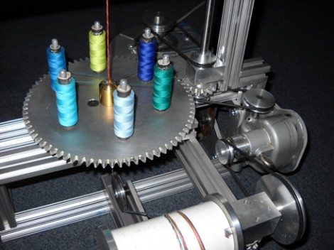
[Robert McMullen] built the machine as part of his degree in Mechanical Engineering at Olin College. But there’s a hobby twist behind its genesis. When he has free time he participates in Olin’s Fire Arts Club and we’re sure this stuff comes in handy. The fuse is made by encapsulating a stream of gunpowder in a tube of woven thread. Twenty spools of thread wrap their way around the nozzle of a fine funnel. Once the casing is in place the machine coats it in a waterproof lacquer.

The image above only shows the base of the machine. All the fun parts (and test burns including one underwater) can be seen in the video after the break. Continue reading “Fuse Making Machine”

TangiBot And The Perils Of Open Source Hardware

I’ve commented before on the terrible inefficiency and artificially high expense of the current crop of 3D printers. It simply doesn’t make sense to produce the plastic parts of 3D printer kits on a printer farm when there are literally thousands of Chinese injection molding companies that will make those parts cheaper. It looks like [Matt Strong] heeded my call and now has a Makerbot Replicator clone up on Kickstarter that costs $700 less than the official version. We assume the Makerbot lawyers are having a busy morning.

From the info on the Kickstarter page, [Matt] is used parts from his Makerbot Replicator to design a one-to-one copy. Every part and component on [Matt]’s TangiBot is 100% compatible – and seemingly 100% identical – with the Makerbot Replicator. Like the Replicator, [Matt] is offering a dual extruder version that allows you to print in two colors.

At the bottom of the Kickstarter page, under a section titled, “How is 3DTangible able to make a Replicator Clone?,” you’ll see [Matt]’s reasoning for cloning the MakerBot replicator. He says everything is open source, and, “MakerBot used other open source designs when designing and producing their 3D Printers.” We’ll agree that MakerBot used existing extruder designs (and improved upon them), but MakerBot was not this blatant in borrowing from the RepRap project.

For want of editorializing, I’ve complained about the stupid inefficiency of manufacturing 3D printers with 3D printers before. It was only a matter of time before someone realized current manufacturing techniques can be used to make 3D printers cheaper. [Matt] – dude – you were supposed to clone a RepRap. Makerbot has done some really incredible things for the community such as building Thingiverse and generally being an awesome cheerleader for the 3D printing community. Taking the flagship Makerbot printer and making it cheaper will not make [Matt] any friends on the Internet, but at least the laws of economics are coming to the world of 3D printers.

Thanks [Brad] for sending this in.

Fortifying Veronica’s VGA Output

[Quinn Dunki] just moved to a new work space and had to pack up her homebrew computer project — called Veronica — in the process. She just unboxed it again and decided now was a good time to fortify the VGA display hardware. It wasn’t in the greatest of shape, since everything for the initial video tests had been built on a breadboard. The transition to protoboard ended up turning out just swell.

One of the thing’s that we like best about [Quinn’s] hacks is that she documents her failures (or perhaps we should just call them hiccups?) just as much as she does her successes. This is not a small thing. We understand, because our own screw-ups don’t usually get photographed due to our raging need to just make the frakking thing work.

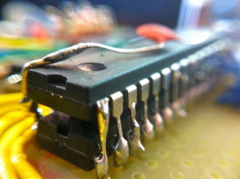
Once she had moved all the components to the new board the circuit was amazingly organized. Since she’s doing high-speed switching with the VGA signals it was important to keep the lines as short and straight as possible, hence the SRAM stack seen above. But when it was first fired up she had a jumble of only-somewhat-organized color stripes. It turns out that she had forgotten to change the color register in the AVR code, the color lines were hooked up in the wrong order, and the switch mode supply was injecting noise into the system. But thanks to her documentation of these issues we’ll know what to do when we find ourselves in a similar situation.