Review: Hands On With The Swarm Satellite Network Eval Kit

If you have devices out in the field, you probably want to connect with them. There was a time when that was hard to do, requiring telephone wires or specialized radio gear. Now cellular data is prevalent, but even cellular isn’t everywhere. If you have the cash, you can pay a number of satellite companies to carry your data, but that’s generally pricey and has its own challenges.

The age of satellite constellations is changing that. Of course everyone by now has heard of Starlink which is offering satellite internet via numerous satellites that are much smaller than traditional telecom satellites. But they’re not the only came in town.

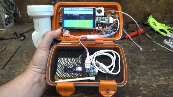
A company called Swarm has put up a constellation of 1/4U cube satellites in low orbits. They offer a ground station that uses an omni antenna and a subscription access program for small amounts of data. They sent us a unit to review, and while I haven’t used the system in a real project yet, the kit was pretty impressive.

About Swarm

Swarm tile device
The Swarm Tile is made to mount on a PCB

The Swarm “tile” is a tiny radio that can talk bi-directionally with small satellites in low Earth orbit. The little unit is made to mount on a PCB, can control its power consumption, and talks to your system via a standard 3.3V UART connection. It does, however, require a small antenna and maybe even a smaller antenna for its GPS module. Small, in this case, is about a mid-size handy talkie antenna. There is a half-wave antenna that doesn’t need a ground plane and a shorter antenna that does need a ground plane.

Continue reading “Review: Hands On With The Swarm Satellite Network Eval Kit”

The Retro Shield, an Arduino Proto Shield for making many different circuits.

Retro Shield Replaces Springs With Jumpers, Includes Blinkenlights!

Is it an AM radio? Yes. It is a 555 LED flashing circuit? Yep. How about a hex counter with a 7 segment display? That too. Five different colored LED’s to satisfy your need for blinkenlights? Even that! What is this magical contraption? Is it one of those old school 30-in-1 or 50-in-1 “Science Fair” kits with the jumper wires and the springs? Almost!

When [grandalf]’s friend showed them a project where a 555 timer was installed on an Arduino shield, they realized two things: This whole “could have done that with a 555 timer” meme is a lot of fun, and “I’ve got an old 556 chip, I wonder if I can build one?” The answer is yes, and so much more.

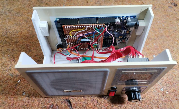
Starting with the 556 timer, and inspired by the old spring-and-jumper kits of the past, [grandalf]’s “556 on a Proto Shield” project evolved into a creation they call the Retro Shield. Snowballing like so many hacker projects, it now includes several built in circuits and components. Breadboard jumpers are used to connect components through strategically placed pin headers, of which there are quite a few!

To make it all fit, some parts were substituted with more compact pieces such as an LM386 instead of an LM380.  The AM radio portion is supplied by an all-in-one radio chip, the ZN414. With the scope creep picking up steam, [grandalf] eventually added so called sidecars- bits of board that contain controls and a speaker hanging off the side of the Proto Shield.

It is not mentioned if the Retro Shield integrates with the Arduino or not. All the same, the Retro Shield has been used to pick up local AM stations, blink LED’s and amplify audio with the LM386. Like [grandalf] we’re sure that the Retro Shield can be used for much more. We hope that [grandalf] expands on the concept and inspires future hackers to answer the question “I wonder what happens if I try this.” 

If you haven’t set eyes on one of the all-in-one kits, check out this 200-in-1 kit teardown and review. And of course, if you have your own hacked up projects to share, be sure to let us know through the Tip Line!

Detect Lightning Strikes With An Arduino

Lightning is a powerful and seemingly mysterious force of nature, capable of releasing huge amounts of energy over relatively short times and striking almost at random. Lightning obeys the laws of physics just like anything else, though, and with a little bit of technology some of its mysteries can be unraveled. For one, it only takes a small radio receiver to detect lightning strikes, and [mircemk] shows us exactly how to do that.

When lightning flashes, it also lights up an incredibly wide spectrum of radio spectrum as well. This build uses an AM radio built into a small integrated circuit to detect some of those radio waves. An Arduino Nano receives the signal from the TA7642 IC and lights up a series of LEDs as it detects strikes in closer and closer proximity to the detector. A white LED flashes when a strike is detected, and some analog circuitry supports an analog galvanometer which moves during lightning strikes as well.

While this project isn’t the first lightning detector we’ve ever seen, it does have significantly more sensitivity than most other homemade offerings. Something like this would be a helpful tool to have for lifeguards at a pool or for a work crew that is often outside, but we also think it’s pretty cool just to have around for its own sake, and three of them networked together would make triangulation of strikes possible too.

Continue reading “Detect Lightning Strikes With An Arduino”

Building A Hundred-Year-Old Radio Transmitter

Our Hackaday team is spread across the world, but remains in easy contact through the magic of the Internet. A number of us hold amateur radio callsigns, so could with a bit of effort and expenditure do the same over the airwaves. A hundred years ago this would have seemed barely conceivable as amateurs were restricted to the then-considered-unusable HF frequencies.

Thus it was that in December 1921 a group of American radio amateurs gathered in a field in Greenwich Connecticut in an attempt to span the Atlantic. Their 1.3 MHz transmitter using the callsign 1BCG seems quaintly low-frequency a hundred years later, but their achievement of securing reception in Ardrossan, Scotland, proved that intercontinental communication on higher frequencies was a practical proposition. A century later a group from the Antique Wireless Association are bringing a replica transmitter to life to recreate the event.

A free-running oscillator is today rarely seen in a radio transmitter, but at the time their single-tube Colpitts oscillator using a UV-204 transmitting tube would have been considered a stable source. That fed a 1KW power amplifier using three more UV-204s in parallel, which in turn fed a Marconi-style T antenna design with an earth counterpoise of multiple radial wires. The replica was originally built for an event in 1996, and substitutes the similar 204A tube for the now unobtainable UV-204. Even then, hundred-year-old tubes are hard to find in 2021, so they could only muster a single working example for the PA.

All in all it’s a very interesting project, and one of which we hope we’ll hear more as the anniversary approaches. If we can get the transmission details we’ll share them with you, and let’s see whether the same distances can be traversed with the more noisy conditions here in 2021.

To demonstrate how advanced this transmitter was for 1921, take a look at the Alexanderson alternator, its mechanical contemporary.

Regen Receiver With Few Parts

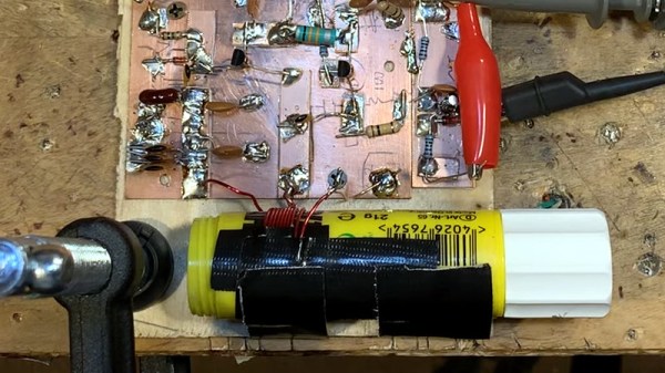
We like regenerative receivers. They perform well and they are dead simple to create. Example? [Radio abUse] modified a few existing designs and built a one-transistor receiver. Well, one transistor if you don’t count the dozens that are probably on the audio amplifier IC, but we won’t quibble. You can watch a video about the simple receiver — which looks good on a neatly done universal board — below.

The coil of #22 wire dominates the visual layout, and we imagine winding it might have been the most time-consuming part of the project. The layout would work with a single-sided PCB and would be a great board to produce by hand if you were inclined to develop that skill.

Regenerative receivers work by holding an amplifier just shy of oscillating at a certain frequency. This provides extremely high gain at a particular frequency which allows just a single stage to really pull in signals.

We were a little sad to find out there was a plan to tear the radio down to build something else. But, we suppose, that’s progress. We’d be tempted to make a module out of the audio amplifier and then keep the RF section intact. But, then again, we have a lot of partial projects like that gathering dust on the shelf, so maybe that’s not such a great idea.

While regenerative receivers aren’t the most common architecture today, they still have their place. The inventor, Edwin Armstrong, developed quite a bit of radio tech that we still use today.

The Curious Case Of The Radio Amateur And The Insulin Pump

A substantial part of gaining and holding an amateur radio licence relates to the prevention of radio interference. In days past this meant interference to analogue television broadcasts, but with ever more complex devices becoming commonplace in homes it applies to much more. This has hit the news in Marion County Florida, where a radio amateur in a senior’s community has shut down his radio station after a potential link emerged between it and another resident’s insulin pump. There is a legal challenge ongoing that relates to the complex’s rules over transmitting antennas.

It’s obviously a serious occurrence for an insulin pump to be affected by anything, and it sounds as though the radio amateur concerned has done the right thing. But it’s clear that something has gone badly wrong in this case whether it’s due to the amateur radio transmissions or not, because for a manufacturer to produce a medical device so easily affected by RF fields should be of concern to everyone. We’d hope that the FCC might take an interest in this story and get to the bottom of it in an impartial manner, because whether it’s the radio amateur at fault, the insulin pump, or something else entirely, it presents a risk to anyone dependent upon such a device.

Perhaps this might also be a case for the ARRL, as we’ve reported before they have some form when it comes to radio investigations.

[Main image source: MailariX, CC-BY-SA 4.0]

Cable Modem Turned Spectrum Analyzer

Hopefully by now most of us know better than to rent a modem from an internet service provider. Buying your own and using it is almost always an easy way to save some money, but even then these pieces of equipment won’t last forever. If you’re sitting on an older cable modem and thinking about tossing it in the garbage, there might be a way to repurpose it before it goes to the great workbench in the sky. [kc9umr] has a way of turning these devices into capable spectrum analyzers.

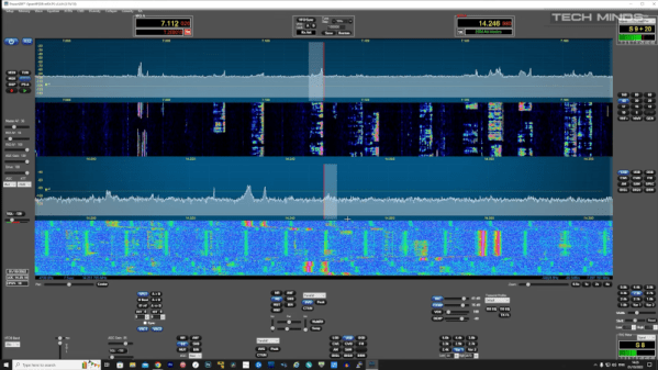
The spectrum analyzer feature is a crucial component of cable modems to help take advantage of the wide piece of spectrum that is available to them on the cable lines. With some of them it’s possible to access this feature directly by pointing a browser at it, but apparently some of them have a patch from the cable companies to limit access. By finding one that hasn’t had this patch applied it’s possible to access the spectrum analyzer, and once [kc9umr] attached some adapters and an antenna to his cable modem he was able to demonstrate it to great effect.

While it’s somewhat down to luck as to whether or not any given modem will grant access to this feature, for the ones that do it seems like a powerful and cheap tool. It’s agnostic to platform, so any computer on the network can access it easily, and compared to an RTL-SDR it has a wider range. There are some limitations, but for the price it can’t be beat which will cost under $50 in parts unless you happen to need two inputs like this analyzer .

Thanks to [Ezra] for the tip!