ice fishing tent and antenna in a snowy field

Ice Fishing Tent Makes Winter Ham Radio Comfy

Cross-pollination between different activities and industries can yield some pretty useful techniques or product combinations, and [Steve] shares some details on using ice fishing gear to make winter ham radio activities more comfortable and portable.

Radio operator inside ice fishing tent in winter
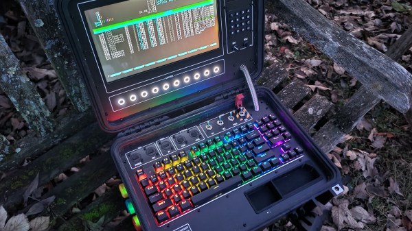
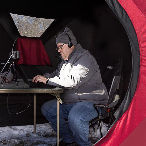
With the help of a folding tent shelter, [Steve] was able to create a minimal and self-contained field station that hosted all his needed equipment, and with the help of a small propane heater, stayed quite comfortable during a 24 hour winter event.

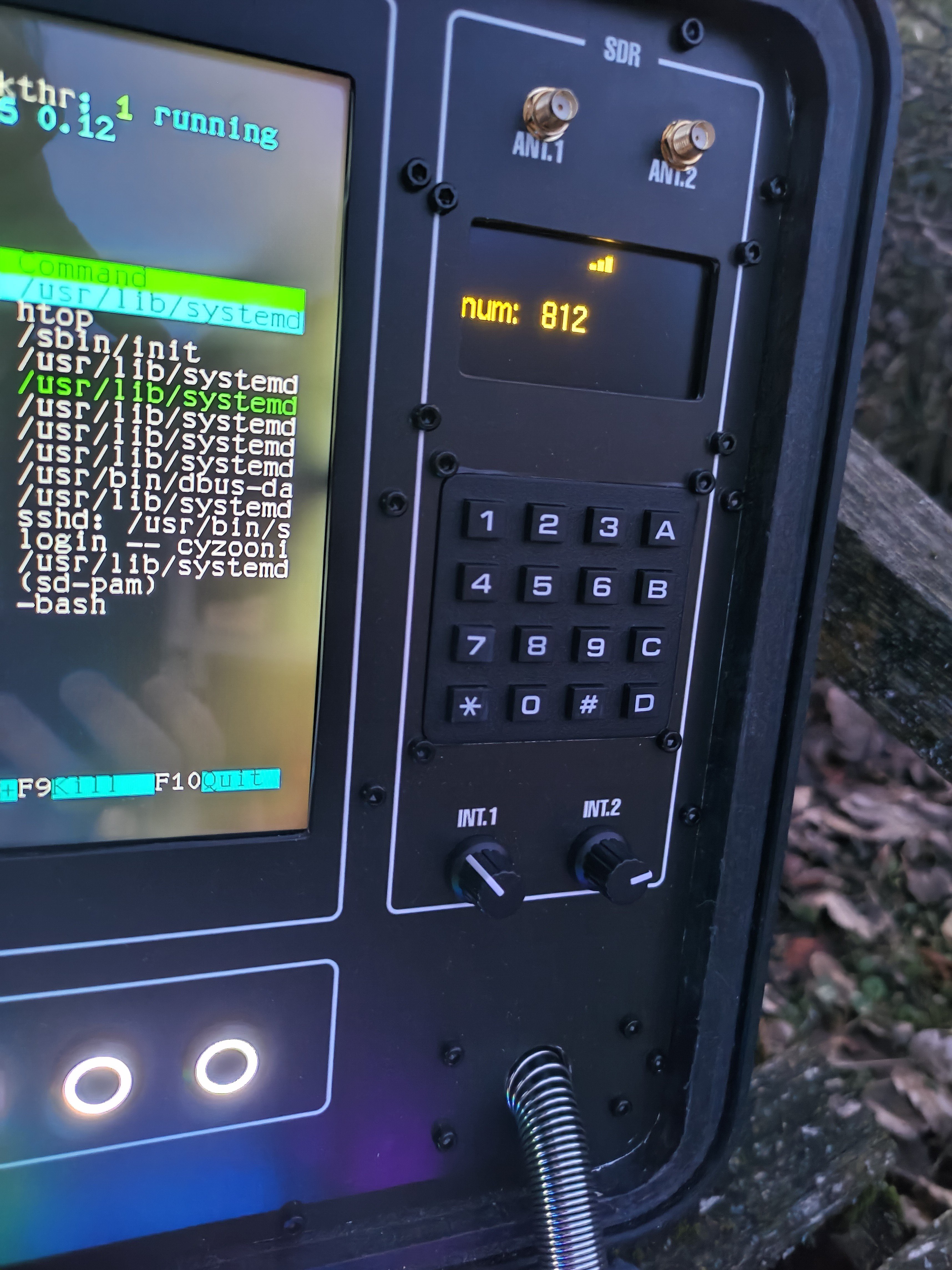
For those interested in the radio end of what [Steve] was doing, he goes into detail about the radio equipment and antenna he used, which itself stows easily into a bag and withstood high winds with success. The goal of the event after all was emergency preparedness, and while radio can operate without a wider infrastructure to support it, antenna design is crucial for best results.

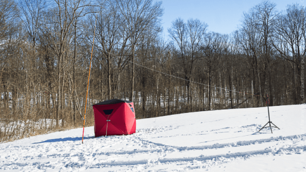
As for keeping the operator safe and sound during all this, it turns out that the problem of a pop-up winter shelter that is both light and compact has already been solved by ice fishers; and while it can be fun to roll one’s own solutions, there’s not always a need to re-invent the wheel.

Retrotechtacular: Measuring TV Audiences With The “Poll-O-Meter”

It may come as a shock to some, but TV used to be a big deal — a very big deal. Sitting down in front of the glowing tube for an evening’s entertainment was pretty much all one had to do after work, and while taking in this content was perhaps not that great for us, it was a goldmine for anyone with the ability to monetize it. And monetize it they did, “they” being the advertisers and marketers who saw the potential of the new medium as it ramped up in early 1950s America.

They faced a bit of a problem, though: proving to their customers exactly how many people they were reaching with their ads. The 1956 film below shows one attempt to answer that question with technology, rather than guesswork. The film features the “Poll-O-Meter System,” a mobile electronic tuning recorder built by the Calbest Electronics Company. Not a lot of technical detail is offered in the film, which appears aimed more at the advertising types, but from a shot of the Poll-O-Meter front panel (at 4:12) and a look at its comically outsized rooftop antenna (12:27), it seems safe to assume that it worked by receiving emissions from the TV set’s local oscillator, which would leak a signal from the TV antenna — perhaps similar to the approach used by the UK’s TV locator vans.

The Poll-O-Meter seems to have supported seven channels; even though there were twelve channels back in the day, licenses were rarely granted for stations on adjacent channels in a given market, so getting a hit on the “2-3” channel would have to be considered in the context of the local market. The Poll-O-Meter had a charming, homebrew look to it, right down to the hand-painted logos and panel lettering. Each channel had an electromechanical totalizing counter, plus a patch panel that looks like it could be used to connect different counters to different channels. There even appears to be a way to subtract counts from a channel, although why that would be necessary is unclear. The whole thing lived in the back of a 1954 VW van, and was driven around neighborhoods turning heads and gathering data about what channels were being watched “without enlisting aid or cooperation of … users.” Or, you know, their consent.

It was a different time, though, which is abundantly clear from watching this film, as well as the bonus ad for Westinghouse TVs at the end. The Poll-O-Meter seems a little silly now, but don’t judge 1956 too hard — after all, our world is regularly prowled by equally intrusive and consent-free Google Street View cars. Still, it’s an interesting glimpse into how one outfit tried to hang a price tag on the eyeballs that were silently taking in the “Vast Wasteland.”

Continue reading “Retrotechtacular: Measuring TV Audiences With The “Poll-O-Meter””

How To Make Laser-cut Decals On The Cheap

Want to make a sweet adhesive decal with a complex design and floating elements, but all you have is a laser cutter and some tape? Good news, because that’s all you need with this method of creating adhesive tape decals on a laser cutter demonstrated by the folks at [Lasers Over Los Angeles]. The overall technique is very similar to creating vinyl decals and using tape transfer to apply them, but is geared towards laser cutters and nice, cheap tape.

This method also makes applying to non-flat surfaces a breeze.

The way it works is this: paper-based tape (such as blue painter’s tape) is laid down in strips on the laser cutter’s honeycomb bed, forming a nice big rectangle big enough for the intended design. Then, the laser cutter cuts vector art into the tape, resulting in an adhesive decal ready to be stuck to some other surface. Transferring is done by using good quality clear packing tape to “pick up” the decal, then move it to where it needs to be.

To do this, one lays strips of packing tape onto the top of the design on the laser bed, then lifts the design up and away. Move the design to its destination (the clear packing tape helps in eyeballing the final position), press the decal onto the final surface, and carefully peel away the clear packing tape. This works because the packing tape sticks only weakly to the back of the painter’s tape; it’s a strong enough bond to hold the decal, but weak enough that the decal will stick to a surface even better.

It’s true that painter’s tape isn’t as durable as vinyl and the color selection is a bit limited, but design-wise one can go as big as the laser bed allows, and the price is certainly right. Plus it’s easily cut by even the most anemic of diode lasers.

Speaking of desktop vinyl cutters, they may have small working areas compared to most laser cutters, but they have some fantastic workshop applications. They can even do home PCB fabrication, by way of knocking out three essential pieces: the etching mask, solder mask, and solder stencil.

A Soft Thumb-Sized Vision-Based Touch Sensor

A team from the Max Planck Institute for Intelligent Systems in Germany have developed a novel thumb-shaped touch sensor capable of resolving the force of a contact, as well as its direction, over the whole surface of the structure. Intended for dexterous manipulation systems, the system is constructed from easily sourced components, so should scale up to a larger assemblies without breaking the bank. The first step is to place a soft and compliant outer skin over a rigid metallic skeleton, which is then illuminated internally using structured light techniques. From there, machine learning can be used to estimate the shear and normal force components of the contact with the skin, over the entire surface, by observing how the internal envelope distorts the structured illumination.

The novelty here is the way they combine both photometric stereo processing with other structured light techniques, using only a single camera. The camera image is fed straight into a pre-trained machine learning system (details on this part of the system are unfortunately a bit scarce) which directly outputs an estimate of the contact shape and force distribution, with spatial accuracy reported good to less than 1 mm and force resolution down to 30 millinewtons. By directly estimating normal and shear force components the direction of the contact could be resolved to 5 degrees. The system is so sensitive that it can reportedly detect its own posture by observing the deformation of the skin due its own weight alone!

We’ve not covered all that many optical sensing projects, but here’s one using a linear CIS sensor to turn any TV into a touch screen. And whilst we’re talking about using cameras as sensors, here’s a neat way to use optical fibers to read multiple light-gates with a single camera and OpenCV.

Continue reading “A Soft Thumb-Sized Vision-Based Touch Sensor”

Rugged Cyberdeck Makes The Case For Keeping Things Water-Tight

Many people build cyberdecks just for the heck of it, and there’s nothing wrong with that at all. On the other hand, [cyzoonic]’s rugged ‘deck is a bit more purpose-built. In this instance, the purpose is software-defined radio.

Underneath those sweet custom-cut panels lies a Raspberry Pi 3B and a BOM full of parts that can be had on Ali Express. There’s also an ESP32 that takes input from the keypad plus the 5 buttons that control the display, and the two potentiometers. [cyzoonic] can dial in frequencies with the knobs, or by punching in digits on the keypad.

One of the problems with using a Pelican case is this — how do you install any type of panel without compromising the case’s water-tightness? [cyzoonic] mentions in the comments that Pelican makes a bracket that allows for panels and things to be screwed down without breaching the case. But in this case, [cyzoonic] made their own brackets in a similar fashion.

Another problem with Pelican cases (and cyberdecks in general that are built into hinged boxen) is something that doesn’t get enough attention: typing ergonomics. Personally, we take comfortable and ergonomic typing fairly seriously, and would love to see a cyberdeck that speaks to this issue.

In the meantime, we’ll have to take [cyzoonic]’s word that while it’s not terribly comfortable to type with the ‘deck on a tabletop, sitting on the floor hunched over the thing like a true hacker is much better. This is a work in progress (at least the IO project anyway), so we’ll be tuning back in occasionally to see if any more instructions appear.

Speaking of ergonomic cyberdecks, here’s the one that drew the line in the sand for us — [Tinfoil_Haberdashery]’s lovely ErgoDox-based NUC machine.

Make It Compatible

I’m probably as guilty as anyone of reinventing the wheel for a subpart of a project. Heck, sometimes I just feel like working on a wheel design. But if that’s the path you choose, you have to think about whether or not it’s important that others can replicate your project. The nice thing about a bog-standard wheel is that everyone has got one.

The case study I have in mind is a wall-plotter project that appeared on Hackaday this week. It’s a really sweet design, and in many ways would be an ideal starter project. I actually need a wall plotter (for reasons) and like a number of the choices made. For instance, having nearly everything, including the lightweight geared steppers on the gondola makes it easy to install and uninstall — you just pin up the timing belt from which it hangs and you’re done. Extra weight on the gondola helps with stability anyway. It’s open source and based on the Arduino libraries, so it should be easy enough to port to whatever microcontroller I have on hand.

But the image-generation toolchain is awkward, involving cutting and pasting into a spreadsheet, which generates a text file in a custom plotting micro-language. Presumably the designer doesn’t know about Gcode, which is essentially the lingua franca of moving machines, or just didn’t feel like implementing it. Where in Gcode, movement commands are like “G1 X100 Y50”, this device expects “draw_line(0,0,100,50)”. They’re essentially equivalent, but incompatible.

I totally understand that the author must have had a good time thinking up the movement commands and writing the spreadsheet that translates SVG files into them. I’ve been there and done that! But if the wall plotter spoke Gcode instead of its own dialect, it would slot instantly into any number of graphics processing workflows, which would make me, the potential user, happier.

When you are looking at reinventing the wheel, think about your audience. If you’re the only person likely to see the project, go ahead and scratch whatever itch you’ve got. You’ll learn more that way. But if you want to share the project with as many people as possible, adhering to the most widely used standards is a good choice for your users, even if it is less fun than dreaming up your own movement language.

Modular Pockit Computer Is More Than Meets The Eye

“Modular” and “Computer” have historically been on the opposite ends of a rather awkward spectrum. One could argue that a hobbyist grade PC is modular, but only to a point. Re-configuring it on the fly is not readily possible. Modular laptops are slowly happening, but what about handheld devices, where our needs might change on a regular basis?

Enter the Pockit: a fully modular IoT/edge computing device that can be reconfigured on the fly without having to reprogram it. Don’t browse away from this page without watching the demonstration video below the break. It just might be the “mother of all demos” for the current decade.

A modular base provides basic computing power in the form of a Raspberry Pi, like many other projects. The base has twelve magnetic connectors, each with twenty I/O and power pins. When a module is added, the operating system detects the new module and loads an appropriate program on the fly. When more modules are loaded, it automatically configures itself so that all modules have a purpose. This allows the Pockit to be an integrated IoT device, an edge computing powerhouse, a desktop computer, a Blackberry-esque handheld, or a touch screen tablet, and so many more things.

For example, if a camera is added, it displays an image on a screen — if there’s  a screen. If a button is added, it automatically takes a picture when the button is pressed. If you want the camera to be motion activated, just add a motion sensor. Done. External devices can be controlled with relays and home automation integrates almost seamlessly.

There are a great number of features that we’re glossing over for the sake of getting to the point: Go watch the video and when you’re done, perhaps you’ll be as astonished as we are. We’ve expressed our love of modular hardware like the Pockit in the past, and after watching this demo, we can only hope that this is what the future of computing and electronics looks like!

Continue reading “Modular Pockit Computer Is More Than Meets The Eye”