We’ve all been there. That sad day when the zipper on our favorite hoodie, bag, or pair of pants breaks in some seemingly irreparable way. But there is hope, and [Magic Stitches] is gonna show you how to make some common repairs using household items and, in some cases, just a little bit of easy hand sewing. After a warm up with a kitchen fork, the video moves on to more significant problems.
The first problem — a chewed-away zipper bottom — is quite common, but requires no sewing to fix. As you’ll see in the video below, all it takes is a drinking straw, some hot glue, a lighter, and a pair of scissors to recreate the plastic bit that keeps the zipper from splitting in twain.
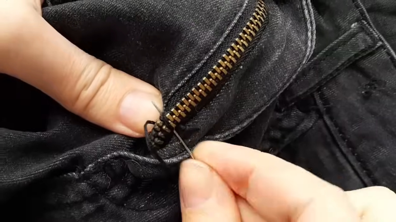 Now the second issue concerns a pair of pants wherein the head has come off the static side of the zipper. This one seems impossible to fix, but [Magic Stitches] cuts into the static side about five teeth from the bottom, slides the head back on, and sews the bottom of the zipper together.
This one we take a little bit of an issue with, because it assumes that you can get your jeans on over your hips without needing the zipper head to be fully down. But what else are you going to do but throw the jeans away upcycle the jeans into a fanny pack or something to immortalize them?