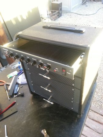
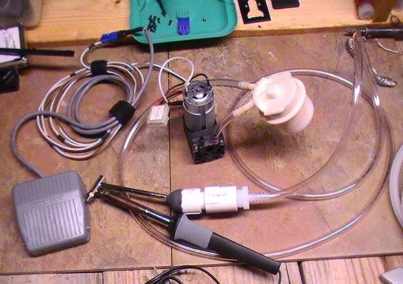
Cooling A Photomultiplier Tube

photomultiplier-tube-cooling-rig

A photomultiplier tube is a device used to measure very low levels of light. It’s a common tool of particle physics when trying to detect just a few photons. It turns out that running a tube at room temperature will not provide the best results. To improve the accuracy and sensitivity of his equipment [David Prutchi] built this thermoelectric photomultiplier tube cooling rig.

You can’t actually see the tube in this image but it looks similar to a vacuum tube or Nixie tube. The difference being that the components inside the glass dome make up the detector instead of an amplifier or filament display. To make a physical interface with the glass [David] wrapped it in magnetic shielding and finished with a layer of aluminum foil tape. This cylinder was then snugly fit inside of an aluminum heat sync. two Peltier coolers were attached to the outside of the heat sync, using Arctic Silver thermal compound to help transmit heat. A thermocouple was also added to monitor the temperature of this first stage of cooling. All of this fits into an aluminum enclosure which was filled with expanding spray foam before having a trio of fan-cooled heat syncs attached to it.

Add Features (that Should Have Already Been There) To An EPROM Programmer

extending-an-eprom-programmer

[Morten Overgaard Hansen] has a cheap EPROM programmer which he uses to program chips for retro gaming (among other things). He was surprised that although the device includes a 40-pin ZIF socket it seems to lack the ability to program 16-bit chips. He figured he could get it to play ball if he put in a little effort. Above you can see that a few add-on parts enabled 16-bit programming on the device.

If you look inside the case you may be surprised to find it uses an FPGA. [Morten] searched around and found a few others online who had been looking to stretch the functionality of these types of programmer. Specifically, he came across a Python program for this programmer’s bigger bother that already implemented the functions necessary to program the larger chips. He used it as a guide when writing his own programming application.

On the hardware side of things he needed to feed a higher voltage to the VCC pin, which is done with the boost converter seen to the right. He also added some jumper wires to manage the output enable signal. To make the whole thing modular he ordered a ZIF socket with long pins and soldered the alterations in place. Look closely and you’ll see two levers for ZIF sockets. The one on the right is for the original socket, the one on the left is for the adapter.

Building A Wooden Air Raid Siren

siren

A while back, [Matthias] was working on a dust collector for his shop. Being the master woodsmith he is, he decided to build a dust collection system out of wood. Everything worked out in the end, but in creating wooden impellers and blowers, he discovered his creations made a lot of noise. For this project, instead of trying to quiet his blower, he decided to make one as loud as possible in the form of an air raid siren.

The basic idea behind [Matthias]’ air raid siren is to make two impellers that force air through two stators along the perimeter of the rotor. As the siren spins, the air coming from the impellers is either blocked or passes through the stators, creating an alternating high and low pressure; to be more accurate, it creates a ton of noise. Stack two of these impellers together and you’ve got a two-tone air raid siren made out of wood.

For something that’s spinning very fast, we’re surprised [Matthias] didn’t have more problems with balancing his siren than he did. There are a few useful tricks to be picked up from his tutorial, though: balancing everything on a marble really seemed to help with the build.

As for how loud the siren is, [Matthias] can’t give us a decibel volume. From the video after the break, though, we can tell you it’s really, really loud.

Thanks [Dimitar] for sending this in. [Matthias], it’s alright if you send projects in yourself. You’ve earned the right to say, “I am so cool!”

Continue reading “Building A Wooden Air Raid Siren”

Coding New Parts In Eagle

chip

Making new parts in Eagle CAD isn’t the easiest thing in the world, especially if you’re dealing with a package that isn’t in one of the default libraries. Usually, making a new part means digging out a datasheet and drawing a new part in Eagle. A better solution would be to generate new parts with code – define the number of pads, the shape of the pads, the symmetry of the chip, and so forth. [Joost]’s madparts does just that, allowing anyone to create new parts in Eagle by entering numbers instead of drawing lines.

The idea behind madparts is to code new entries in Eagle libraries with Coffeescript. It has instant graphical feedback for the part you’re designing, and is able to import from and export to Eagle libraries. A KiCAD-enabled release is coming soon, but until then, madparts looks like a great way to create your own parts in weird packages in Eagle.

Turning PCBs Into Art

Designing a circuit, laying out a board, and sending it off to be fabbed is so easy anyone can do it. A lot of people are, in fact, and with the traditional tools like KiCAD and Eagle, a lot of different boards look very, very similar. You could always add some cool silkscreen graphics to your board to make it stand out, but [Saar] has a better solution: it’s called PCBmodE, and it allows you to draw circuits artistically instead of the 45° angles we’ve become so accustomed to.

PCBmodE takes the parts, pads, signals, and vias for boards stored in JSON files and converts them to an SVG representation. The file is then routed (manually, but [Saar] is working on automated routing) and Gerberized so it can be sent off to a production house.

You can grab PCBmodE over on bitbucket, but right now it’s still a very early version. Vias and copper pours are working, but [Saar] has only fabbed this board so far.

Giving A CNC Knitting Machine A New Brain

We’re all about big machines that build things for us – laser cutters, CNC mills, and 3D printers are the machines de rigueur for Hackaday.  Too often we overlook the softer sides of fabrication that include textiles and knitting. [varvara] and [mar] are doing their best to bring us the softer side of things with their modification of a Brother knitting machine. They call their build Knitic, and it’s a great way to knit with computer control.

Instead of previous Brother knitting machine hacks we’ve seen, Knitic doesn’t bother with emulating the keypad or controlling the microprocessor already there; this build dispenses with the Brother brain and controls the solenoids and switches of the knitting machine directly with the help of an Arduino and a home-etched shield.

It’s not quite an automated knitting machine – someone still has to run the shuttle across the machine – but the patterns are controlled via a Processing app available on the Knitic github. You can check out [Varvara]’s demo of Kinitic after the break.

Continue reading “Giving A CNC Knitting Machine A New Brain”

Rigol WFM Viewer Ported For Non-Windows Users

rigol-wfm-parser-for-linux

[Matthias Blaicher] may think this isn’t a big deal when it comes to the amount of work he put into the hack. But for us, anything that extends the functionality of the versatile yet affordable Rigol DS1052E is a win. In this case he’s taken a previous hack and made it work for more people by extending the functionality of the WFM file format viewer.

[Dexter2048] pulled off the original hack which allows this oscilloscope to be used as a spectrum analyzer. [Matthias] didn’t want the tool to be limited to running only on Windows systems so he got to work. This isn’t quite as easy as sounds because the only part of the original code that was released is the parser itself. [Matthias] had to build everything up from that starting point. His software uses standard Python to parse the WFM file and reformat the data. The features included in the current version allow you to export data as a CSV file and even plot the waveform and FFT as seen above.