The SSD described, a green board with a ZIP connector, a controller chip and two out of four NAND chips populated. There's traces of flux on the chip, as it hasn't been washed after soldering yet.

ZIF HDDs Dying Out? Here’s An Open-Source 1.8″ SSD

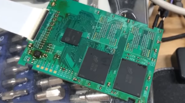
A lot of old technology runs on parts no longer produced – HDDs happen to be one such part, with IDE drives specifically being long out of vogue, and going extinct to natural causes. There’s substitutes, but quite a few of them are either wonky or require expensive storage medium. Now, [dosdude1] has turned his attention to 1.8 ZIF IDE SSDs – FFC-connected hard drives that are particularly rare and therefore expensive to replace, found in laptops like the Macbook Air 1,1 2008 model. Unsatisfied with substitutes, he’s designed an entire SSD from the ground up around an IDE SSD controller and NAND chips. Then, he made the design open-source and filmed an assembly video so that we can build our own. Take a look, we’ve put it below the break!

For an open-source design, there’s a respectable amount of work shared with us. He’s reverse-engineered some IDE SSDs based on the SM2236 controller to design the schematic, and put the full KiCad files on GitHub. In the video, he shows us how to assemble this SSD using only a hot air station and a soldering iron, talks about NAND matching and programming software intricacies, and shows the SSD working in the aforementioned Macbook Air. Certainly, assembly would have been faster and easier with a stencil, but the tools used work great for what’s a self-assembly tutorial!

Continue reading “ZIF HDDs Dying Out? Here’s An Open-Source 1.8″ SSD”

Stock Looking PSP Hides A Raspberry Pi Zero

We don’t see that many PSP hacks around these parts, perhaps because the system never attained the same sort of generational following that Nintendo’s Game Boy line obtained during its heyday. Which is a shame, as it’s really a rather nice system with plenty of hacking potential. Its big size makes it a bit easier to graft new hardware into, the controls are great, and there’s no shortage of them on the second-hand market.

Hopefully, projects like this incredible “PiSP” from [Drygol] will inspire more hackers to take a second look at Sony’s valiant attempt at dethroning Nintendo as the portable king. With his usual attention to detail, he managed to replace the PSP’s original internals with a Pi Zero running RetroPie, while keeping the outside of the system looking almost perfectly stock. It wasn’t exactly a walk in the park, but we’d say the end definitely justifies the means.

The first half of the project was relatively painless. [Drygol] stripped out all the original internals and installed a new LCD which fit so well it looks like the thing was made for the PSP. He then added a USB Li-ion charger board (complete with “light pipe” made out of 3D printer filament), and an audio board to get sound out of the usually mute Pi Zero. He had some problems getting everything to fit inside of the case. The solution was using flat lithium batteries from an old Nokia cell phone to slim things down just enough to close up the PSP’s case with some magnets.

What ended up being the hardest part of the build was getting the original controls working. [Dyrgol] wanted to use the original ZIF connector on the PSP’s motherboard so he wouldn’t have to modify the stock ribbon cable. But it was one of those things that was easier said than done. Cutting out the section of PCB with the connector on it was no problem, but it took a steady hand and a USB microscope to solder all the wires to its traces. But the end result is definitely a nice touch and makes for a cleaner installation.

We’ve covered the exciting world of PSP homebrew, and even DIY batteries built to address the lack of original hardware, but it’s been fairly quiet for the last few years. Here’s hoping this isn’t the last we’ve seen of Sony’s slick handheld on these pages.

Continue reading “Stock Looking PSP Hides A Raspberry Pi Zero”

Fixing An NES For Good

Sometime in the late 80s, the vast collective consciousness of 8-year-olds discovered a Nintendo Entertainment System could be fixed merely by blowing on the cartridge connector. No one knows how this was independently discovered, no one knows the original discoverer, but one fact remains true: dirty pins probably weren’t the problem.

The problem with a NES that just won’t read a cartridge is the ZIF socket inside the console. Pins get bent, and that spring-loaded, VCR-like front loader assembly is the main point of failure of these consoles, even 30 years later. You can get replacement ZIF sockets for a few bucks, and replace the old one using only a screwdriver, but this only delays the inevitable. That ZIF socket will fail again a few years down the line. Finally, there is a solution.

The Blinking Light Win, as this project is called, replaces the ZIF connector with two card-edge slots. One slot connects to the NES main board, the other to the cartridge connector. There’s a plastic adapter that replaces the spring-loaded push down mechanism created for the original ZIF connector, and installation is exactly as easy as installing a reproduction NES ZIF connector.

If you’re wondering why consoles like the SNES, Genesis, and even the top-loader NES never had problems that required blowing into the cartridge connector, it’s because the mere insertion of the cartridge into the slot performed a scrubbing action against the pins. Since the ZIF socket in the O.G. NES didn’t have this, it was prone to failure. Replacing the ZIF with a true card-edge slot does away with all the problems of dirty contacts, and now turns the NES into something that’s at least as reliable as other cartridge-based consoles.

Add Features (that Should Have Already Been There) To An EPROM Programmer

extending-an-eprom-programmer

[Morten Overgaard Hansen] has a cheap EPROM programmer which he uses to program chips for retro gaming (among other things). He was surprised that although the device includes a 40-pin ZIF socket it seems to lack the ability to program 16-bit chips. He figured he could get it to play ball if he put in a little effort. Above you can see that a few add-on parts enabled 16-bit programming on the device.

If you look inside the case you may be surprised to find it uses an FPGA. [Morten] searched around and found a few others online who had been looking to stretch the functionality of these types of programmer. Specifically, he came across a Python program for this programmer’s bigger bother that already implemented the functions necessary to program the larger chips. He used it as a guide when writing his own programming application.

On the hardware side of things he needed to feed a higher voltage to the VCC pin, which is done with the boost converter seen to the right. He also added some jumper wires to manage the output enable signal. To make the whole thing modular he ordered a ZIF socket with long pins and soldered the alterations in place. Look closely and you’ll see two levers for ZIF sockets. The one on the right is for the original socket, the one on the left is for the adapter.

Automated Chip Burning

[Alexsoulis] needed to burn the Arduino bootloader to a slew of ATmega328 chips. Instead of sitting there and plugged the chips into a programmer one at a time, he build a robotic microcontroller programmer.

It starts with the DIP package microcontrollers in a tube, with a servo motor to dispense them one-by-one. An arm swings over and picks up the chip with a fish pump powered vacuum tweezers similar to the pick-and-place head we saw recently. From there the chip is dropped into a ZIF socket and programmed by an Arduino. Once the process is complete it is moved to the side and the process repeats.

We’ve reported on using an Arduino as an AVR programmer but we’ve never actually done it ourselves (we use an AVR Dragon programmer). Take a look at the video after the break and let us know if you think the actual programming seems incredibly slow.

Continue reading “Automated Chip Burning”

Programmable Game Boy Cartridge Walk Through

We looked at [Gerry’s] PLCC based programmable Game Boy cartridge back in May and mentioned that he was working on a how-to video. He did quite a bit more than that. He’s made a PDF version of the instructions but went into deep detail with a collection of four videos on his YouTube channel. We’ve embedded all four after the break. They include an introduction and background about the cartridges, desoldering the ROM chip, preparing sockets and wire, and making the solder connections. Whether you’re interested in this particular hack or not, seeing [Gerry’s] soldering practices make the videos worth watching.

Continue reading “Programmable Game Boy Cartridge Walk Through”

AVR Dragon Wiring Alternative

dragon_jumper_board

We love our AVR Dragon programmer. It is a small board with a lot of functionality: in-circuit serial programming, JTAG, debug wire, and high voltage serial programming. Unfortunately, out of the box it is not quite ready for action. The Dragon ships with an unpopulated prototyping area and missing a pin header for the HVSP. For most people this means soldering on pin headers and a ZIF socket then jumpering between the various programming headers and the header for the socket. Tired of working with jumper wires, [Jussi] designed a small PCB to make the connections (original link in Finnish). Continue reading “AVR Dragon Wiring Alternative”