Adding An Optical Mouse Sensor To An Autonomous Vehicle

[Tim] is getting his drone ready for SparkFun’s 2013 Autonomous Vehicle Competition on June 8th. He has a pretty good start, but was having some problems accurately measuring travel distance. The technique he chose for the task was to glue magnets onto the axles of the vehicle and monitor them with a hall effect sensor. Those sensors are finicky and a few problems during testing prompted him to look at a redundant system. Right now he’s experimenting with adding an optical mouse sensor to the autonomous vehicle.

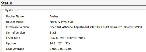
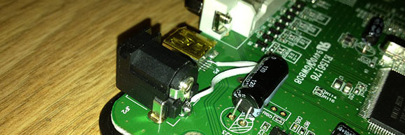
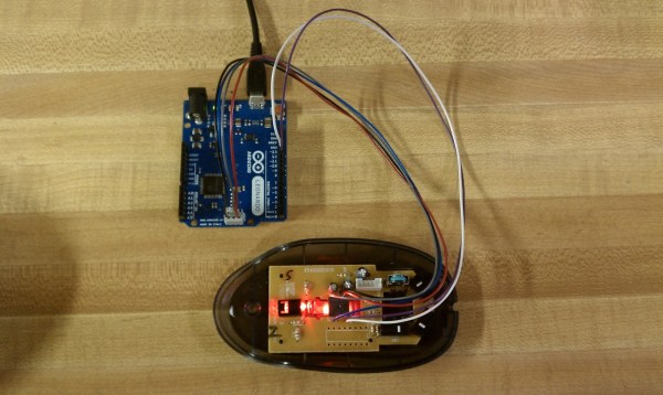
Recently we saw the same concept used, but it was meant for tracking movement of a full-sized automobile. If it can work in that application it should be perfect here since the vehicle is much closer to the ground and will be used in ideal conditions (flat pavement with clear weather). [Tim] cracked open an old HP mouse he had lying around. Inside he found an Avago ADNS-5020 sensor. After grabbing the datasheet he discovered that it’s simply an I2C device. Above you can see the Arduino Leonardo he used for the first tests.

[Tim] coded functions to monitor the chip, including some interesting ones like measuring how in-focus the surface below the sensor is. This brings up a question, is there limit on how fast the vehicle can travel before the sensor fails to report back accurately?

Hall Effect Limit Switches For A 3D Printer

hall-effect-limit-switches

We’re used to thinking of limit switches as a mechanical device that cuts the motor connection before physical damage can occur. [Anthony] decided to try a different route with this project. He built this set of no-contact limit switches using a hall effect sensor. The small black package sticking out past the end of the protoboard is the sensor. It is used to detect a magnetic field.

[Anthony] chose to use an Allegro A3144 sensor. Apparently it is no longer in production but was easy to find for a song and dance on eBay. When thinking about the design he decided to add two LED indicators, one lights when the switch is open and the other when it has been tripped. This would have been easy to do with just one LED, but he needed to add more parts to get both working. In the lower left corner of the protoboard you can see the configurable gate device (74LVC1G58) he added to monitor the hall effect sensor and switch the output and LEDs accordingly.

Microscope Ring Light With A Number Of Different Features

microscope-ring-light

Microscopes magnify light. It makes sense that having more light reflecting off of the subject will result in a better magnified image. And so we come to Aziz! Light! It’s [Steve’s] LED light ring for a stereo microscope. It’s also a shout out to one of our favorite Sci-Fi movies.

He’s not messing around with this microscope. We’ve already seen his custom stand and camera add-on. This is no exception. The device uses a fab-house PCB which he designed. It boasts a dual-ring of white LEDs. But the controls don’t simply stop with on and off. He’s included two rotary encoders, three momentary push switches, and three LEDs as a user interface. This is all shown off in his demo video after the break.

An ATtiny1634 is responsible for controlling the device. When turned on it gently ramps the light up to medium brightness. This can be adjusted with one of the rotary encoders. If there are shadows or other issues one of the push buttons can be used to change the mode, allowing a rotary encoder to select different lighting patterns to remedy the situation. There are even different setting for driving the inner and outer rings of LEDs.

We haven’t worked with any high-end optical microscopy. Are these features something that is available on commercial hardware, or is [Steve] forging new ground here?

Continue reading “Microscope Ring Light With A Number Of Different Features”

Building A Theremincello

building-a-theremin-cello

We totally missed the ball on this project. It should have been run on April Fools’ day and you would have no idea if it were real or a hoax. That’s because the very serious performance given after the break is hard to watch without a least a bit of a chuckle. The instrument shown above is a Theremincello. It’s an instrument in the shape of a cello which functions in a similar way to a Theremin.

The instrument being played in that video clip is the first generation and the one pictured above is its successor. The creator wanted to refine the electronics so that the resulting sound wasn’t so ‘flutey’. The result can be heard on the video embedded in this Theremin World article and we think they’ve accomplished the goal; it sounds much better! In the clip [Thierry Frenkel] demonstrates changing notes on the fingerboard with the left hand. The right hand which would normally bow the strings operates the lever to adjust the volume of the note being played back.

If a single fingerboard isn’t enough for your needs you may consider building this four-track design instead.

Continue reading “Building A Theremincello”

Homebuilt Laser Cutter Ideas

Laser-Cutter

[Wuzabear] wrote in to tell us about this “DIY Laser Cutter for PCB Stencils.” While a full BOM and step-by-step build instructions aren’t provided for the frame, pictures of the build are available, and some different options for construction are discussed. One other option that was especially interesting would be to use a ready-built RepRap or other 3D printer to act as the laser motion controller. Apparently this has been experimented with, and we’d love to see any versions that or readers have come up with!

Besides some different ideas and resources for the moving parts of the cutter, there is some information on how to hook up a laser for this purpose, as well as  for the software and calibration required. It should be noted that you should always wear the appropriate safety goggles if you’re working with a high-powered laser. Although any machine-tool can be dangerous, lasers provide some safety issues that should be treated with extreme caution.

Upgrading A Router With Impeccable Soldering Skills

router

[Necromant] recently acquired a router that was nearly free. Looking his gift horse in the mouth, he hooked up a serial port to see if it could run some updated firmware such as OpenWRT. The initial findings were promising; it used the same CPU as the very popular WR703N, but this free router only had 2 MiB of Flash and 8 MiB of RAM – barely enough to do anything. His solution to this problem is in the true hacker tradition: just solder some more chips onto the router.

Upgrading the RAM was comparatively easy; [Necromant] found an old stick of RAM, desoldered one of the chips, and replaced the measly 8 MiB chip with a new 64 Megabyte chip.

The Flash, though, proved more difficult. Without the right code in the Flash for the radio test, the router wouldn’t be useful at all. The solution was to read the original 2 MiB chip, read the Flash from a  WR703, and combined the two with a simple dd command. This was written to a new SPI flash chip with a buspirate and a home etched board.

Powering The Oculus Rift With USB

rift

Oculus Rift dev kits are starting to make their way onto the workbenches of makers around the globe. Some are even going so far as to tear open the hardware and see how they can improve it. [Mike] didn’t like the fact the Oculus Rift needed a wall wart power supply, so he modded it so it can be powered over a USB port.

The key insight for this mod comes after [Mike] put a Kill-a-Watt between his outlet and the Rift’s power adapter. He found only 600 mA of current was being used by the Rift, assuming 100% efficiency in the adapter. A USB port is supposed to provide 500 mA of current, so with a soldering gun, [Mike] bridged the DC input jack and the USB port on the Rift. Perhaps unsurprisingly, everything worked perfectly.

In case you’ve forgotten, Hackaday is getting one of these Oculus Rift dev kits. We’ll post a teardown when [Caleb] learns to share. You can check out a video of [Mike]’s modded Rift and some dolla dolla billz after the break.

Continue reading “Powering The Oculus Rift With USB”