A vacuum tool is an invaluable tool if you’re working with tiny SMD parts, and even with tweezers you might have a hard time placing these nearly invisible components on their pads for soldering. One tool that’s really great for these parts is a vacuum pen, usually made from an old aquarium air pump. [Jon] may have found a much more suitable piece of equipment to scavenge for a vacuum pen build – a nebulizer.
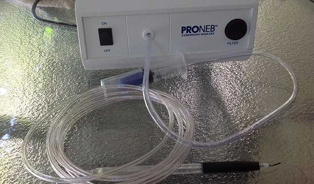
Nebulizers provide asthmatics with low pressure, low volume air to atomize medication for inhalation. Inside the nebulizer is a small diaphragm pump, just like the small aquarium pump teardowns we’ve seen. In just five minutes, [Jon] tore his thrift store nebulizer apart and reversed the flow of air, turning something that blows into something that sucks.
After the suction part of the build was finished, [Jon] needed a way to pick up small components. He did this by blunting a large hypodermic needle and fastening it to the end of a Bic pen with heat shrink tubing. After drilling a small hole in the pen body, he had a very nice looking SMD vacuum pump.