Breadboards Go To Pot

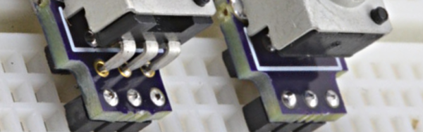
Solderless breadboards are great for ICs and discrete components like resistors, capacitors, and transistors (at least the through hole kind). They aren’t so good at holding big components like potentiometers. Sure, you can jam trimmers in maybe. You can also solder leads to a pot, but that’s not pretty and tend to pull out when handled. [PaulStoffregen] got tired of it, so he put together some good looking PC boards that mount a 6mm shaft pot securely to a breadboard.

[Paul] noticed that having delicate or knobless adjustments on a breadboard inhibited people from playing with demo circuits. The new set up invites people to make adjustments. The pictures and video show an early version with six pins, but [Paul] added two more pins on the recent batch to increase the grip of the breadboard.

Continue reading “Breadboards Go To Pot”

Literal Breadboard Hack Forces It To Accept Dual Pin Headers

Usually when there is a clear demand for something, some entrepreneur will fill that demand. Unfortunately, no one seems to think there’s a need for a solderless breadboard product that can handle boards that have a dual row header. These devices have 0.1″ spacing in both directions, so while they will fit in a standard breadboard, the contacts will short out the adjacent pins on the device, which makes it worthless.

[Baz] needed to connect an RF24L01 module to a breadboard. Instead of connecting leads to the device or devising a breakout board, [Baz] actually hacked his breadboard. To make an area to plug in a dual row device, he took the breadboard apart, pulled the spring contacts, cut them, and then put them back in.

Of course, you have to make sure the cut is wide enough that the two parts of the spring won’t touch. It looks like [Baz] used a small screwdriver to help the springs keep their shape and cut them with simple diagonal cutters.

Continue reading “Literal Breadboard Hack Forces It To Accept Dual Pin Headers”

A Stack Of Boards For An Edison Breadboard Adapter

The Intel Edison is a neat piece of hardware, but the connector for the Edison is extremely intimidating and the Mini breakout board is incompatible with breadboards. What’s [Federico], a builder of Internet of Things to do? Etch their own breakout board.

The Mini Breakout board for the Intel Edison is the official ‘minimal’ offering for getting the Edison up and running with a mess of jumper wires and LEDs. While this breakout board handles the USB to UART bridge, power regulation, and exposes all the pins on the Edison connector, it is terrible for prototyping. It’s a 4×14 array of holes on a 0.1″ grid that are hidden underneath the Edison.

[Federico] handled this problem with a copper clad board and a little bit of ferric chloride. He jumped into Eagle and created a breakout board to turn the 4×14 pin grid into a more sensible breadboard-friendly layout.

The breadboard-friendly adapter doesn’t have level shifters, but by using the mini-breakout board between the Edison and the breadboard adapter [Federico] still has the UART to USB hardware and a battery charging circuit. Still, there’s room for improvement and we can’t wait to see what he comes up with next.