Active Ideal Full Bridge Rectifier Using TEA2208T

Everyone loves a full-wave bridge rectifier, but there’s no denying that they aren’t 100% efficient due to the diode voltage drop. Which isn’t to say that with some effort we cannot create an ideal bridge rectifier using active components, as demonstrated by [Mousa] with an active bridge circuit. This uses the NXP TEA2208T active bridge rectifier controller, along with the requisite four MOSFETs.

Comparing a diode bridge rectifier with an active bridge rectifier. (Credit: Mousa, YouTube)

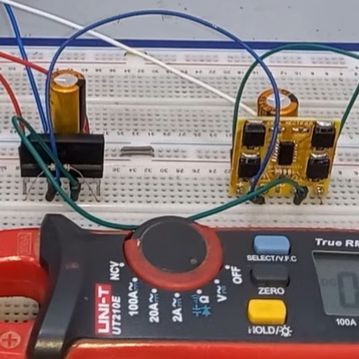
Taking the circuit from the datasheet, a PCB was created featuring four FDD8N50NZ MOSFETs in addition to the controller IC. These were then compared to a diode-based bridge rectifier, showing the imperfections with the latter when analyzing the output using an oscilloscope.

As expected, the active rectifier’s output was also one volt higher than the diode bridge rectifier, which is another small boost to overall efficiency. According to NXP’s product page, there’s about a 1.4% efficiency gain at 90 VAC, with the chip being promoted for high-efficiency operations. When you consider that many designs like computer PSUs feature one or more diode bridge rectifiers often strapped to heatsinks, the appeal becomes apparent. As for [Mousa], he put this particular board in his laboratory PSU instead of the diode bridge rectifier, because why not.

Perhaps the biggest impediment to using an active rectifier is the cost, with the TEA2208T coming in at $4 on DigiKey for a quantity of 100, in addition to the MOSFETs, PCB, etc. If power efficiency isn’t the goal, then some wasted power and an aluminium heatsink is definitely cheaper.

Continue reading “Active Ideal Full Bridge Rectifier Using TEA2208T”

Investigating A New Chip In A Minimalist LED Lamp

Teardowns of cheap electronic devices can produce results that are interesting, horrifying, or both, especially when mains power is involved. [bigclivedotcom] gave a minimalist LED lamp his reverse engineering treatment, and discovered a new chip that requires only four additional passive components to run LEDs on AC power.

The chip in question is a Joulewatt JWB1981, for which no datasheet is available on the internet. However, there is a datasheet for the JW1981, which is a linear LED driver. After reverse-engineering the PCB, [bigclivedotcom] concluded that the JWB1981 must include an onboard bridge rectifier. The only other components on the board are three resistors, a capacitor, and LEDs. The first resistor limits the inrush current to the large smoothing capacitor. The second resistor is to discharge the capacitor, while the final resistor sets the current output of the regulator. 

It is possible to eliminate the smoothing capacitor and discharge resistor, as other LED circuits have done, which also allow the light to be dimmable. However, this results in a very annoying flicker of the LEDs at the AC frequency, especially at low brightness settings.

As always, this is a very informative video from [bigclivedotcom], and it was all done based on a single picture of the PCB sent in by a viewer. He also mentions that the lifespan of the lamp would likely be increased by swapping out the current setting resistor for a larger one.

We’ve covered several [bigclivedotcom]’s videos, covering topics from self-powered wireless switches to filling up fake capacitors with electrolyte.

Continue reading “Investigating A New Chip In A Minimalist LED Lamp”

Fixing The Flicker Afflicting A Night Light

It’s hard to part with some things, even if they’re broken and were worth next to nothing to begin with. But some things are just special, y’know? And we would say in this case, the thing was definitely worth saving.

[Taste the Code]’s daughter’s beloved night light had a terrible flickering problem, and then stopped working altogether. Eager to make her happy, he cracked it open and found that one of the wires had disconnected from the outlet pin it was soldered to. That’s a simple enough fix, but trying to solder in tight quarters where the walls are soft plastic can be quite challenging.

Once that was fixed, [Taste the Code] plugged it in to a test outlet. It’s back to working, but also back to flickering, because there is no capacitor to smooth out the signal going to the LEDs. [Taste the Code] measured the voltage drop across the output of the bridge rectifier and soldered in an electrolytic cap with more than double the necessary voltage rating, just to be safe. You can check out the video after the break.

This goes to show several things: one, you can learn from fixing and improving cheap electronics from the likes of your local dollar store. Two, you can also get some kinds of components there quite inexpensively from things like magnetic sensor-based window alarms and dirt cheap solar garden lights.

You can also do some fun stuff with those cheap IKEA lamps designed for children. Here’s an adorable cloud lamp with an RGB LED upgrade that shows the weather mood using an ESP8266.

Continue reading “Fixing The Flicker Afflicting A Night Light”

Scope Noob: Bridge Rectifier

Welcome back to this week’s installment of Scope Noob where I’m sharing my experiences learning to use my first oscilloscope. Last week I started out measuring mains frequency using an AC-AC wall wart adapter. Homework, for those following along, was to build a bridge rectifier and probe the signals from it. Let’s take a look.

Continue reading “Scope Noob: Bridge Rectifier”

DVD Power Supply Repair Tips

bridge-rectifier-repair

This demonstration fixes the power supply of a DVD player, but the skills transcend this one application. [Alan] walks us through the process of repairing a power supply (translated) on a simple consumer electronics unit.

Obviously this starts by cracking open the dead device and verifying that the culprit is the power supply. [Alan] then removes that board from the chassis and gets down to work with a visual inspection. He’s got several images which illustrate things to look for; blistered electrolytic capacitors, cracked solder joins, scorch marks, etc. In his case there’s obviously a burnt out fuse, but that merely protects the hardware from further damage, it’s not the cause. Next he examines the diodes of the bridge rectifier. These need to be removed from the system to do so, which he accomplishes by clipping one end of each as seen above. He found that two diodes on one side of the bridge had broken down. After replacing them he tries a new fuse which immediately burns out. But a quick swap of the capacitors and he gets the thing back up and running.

We perk up every time we see this type of repair hack. We figure if we can build our own hobby electronics we should be able to fix the cheap devices like this one.

Experimenting With Bridge Rectifers For AC To DC Power Conversion

The folks over at Toymaker Television have put together another episode. This time they’re looking at bridge rectifiers and how they’re used in AC to DC converters.

This is a simple concept which is worth taking the time to study for those unfamiliar with it. Since Alternating Current is made up of cycles of positive and negative signals it must be converted before use in Direct Current circuits; a process called rectification. This is done using a series of 1-way gates (diodes) in a layout called a bridge rectifier. That’s the diamond shape seen in the diagram above.

This episode, which is embedded after the break, takes a good long look at the concept. One of the things we like best about the presentation is that the hosts of the show talk about actual electron flow. This is always a quagmire with those new to electronics, as schematics portray flow from positive to negative, but electron theory suggests that actual electron flow is the exact opposite. Continue reading “Experimenting With Bridge Rectifers For AC To DC Power Conversion”